
Manufacturing Control System Troubleshooting: 2026 Guide
Manufacturing control system troubleshooting is the process of systematically diagnosing and resolving faults in automation equipment to restore production with minimal downtime. Technicians who follow a structured methodology, rather than guessing at causes, resolve faults faster and avoid repeat failures. This guide covers the tools, safety protocols, step-by-step diagnosis methods, and legacy system repair practices that manufacturing professionals need in 2026. Industrialpartsusa supports this process with same-day shipping on hard-to-find PLC modules, I/O cards, and legacy automation components.
What tools and safety protocols do you need before troubleshooting?
Effective industrial control troubleshooting starts with the right equipment. A calibrated digital multimeter measures voltage, current, and continuity. A loop calibrator tests 4–20 mA analog signals without disconnecting field devices. A thermal imaging camera identifies overheating components before they fail completely. An oscilloscope captures signal noise and transient spikes that a multimeter misses.
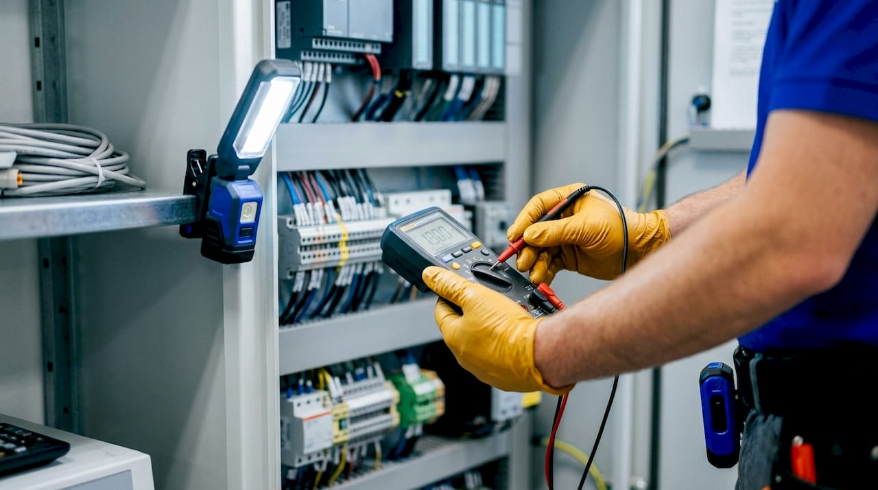
Safety is non-negotiable before any panel work. NFPA 70E and Lockout/Tagout (LOTO) procedures require you to verify zero energy state with calibrated test equipment before touching any live components. LOTO means physically locking out every energy source, including pneumatic and hydraulic lines, not just electrical feeds. The one-hand rule, keeping one hand behind your back when probing live circuits, reduces the current path through your chest and lowers shock risk significantly.
Personal protective equipment (PPE) requirements under NFPA 70E depend on the arc flash hazard category of the panel. At minimum, wear arc-rated gloves, safety glasses, and a face shield rated for the incident energy level of the equipment. Never assume a panel is de-energized because a breaker is open.
- Multimeter: Verify voltage levels, continuity, and resistance across terminals
- Loop calibrator: Simulate and measure 4–20 mA signals for sensor and transmitter testing
- Thermal camera: Spot overheating contactors, fuses, and bus bars before failure
- Oscilloscope: Detect signal noise, ground loops, and transient spikes on control wiring
- PPE: Arc-rated gloves, face shield, and safety glasses matched to arc flash category
- LOTO hardware: Padlocks, hasp, and lockout tags for every energy isolation point
Pro Tip: Always verify zero energy with your multimeter after applying LOTO. A breaker that appears open can still pass voltage through a welded contact or a backfed circuit.
How do you systematically diagnose manufacturing control system faults?
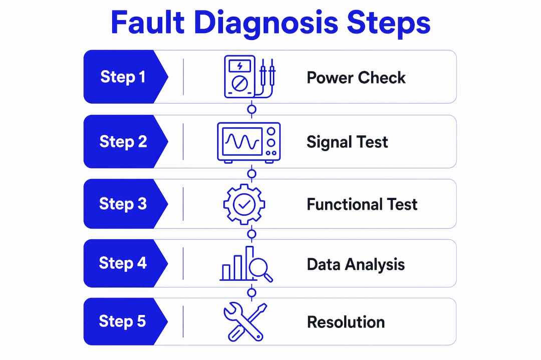
A structured approach to manufacturing control system troubleshooting prevents the most common error: changing software before verifying hardware. Sudden faults rarely originate in program logic. Follow these five steps in order.
-
Check power supplies and voltage tolerances. Control panel power supplies must maintain ±5% voltage tolerance. Voltage outside this band causes erratic PLC behavior, sensor dropouts, and false fault codes. Measure DC bus voltage at the power supply output terminals and at the PLC backplane connector. A reading that drifts under load points to a failing supply, not a software bug.
-
Read LED and fault indicators. Every PLC, including GE Fanuc Series 90-30 and RX3i racks, uses LED indicators to communicate status. A solid red fault LED on a CPU module means the processor has halted. A flashing I/O status LED points to a specific rack or module. Read these indicators before connecting programming software.
-
Inspect I/O modules and field wiring. 80% of automation faults originate in field devices, sensors, wiring, and actuators, not in the PLC program. That figure means your first physical check should be at the terminal strip, not the laptop. Measure signal presence at the I/O module input terminal and compare it to the field device output. A signal present at the device but absent at the module points to a wiring fault or blown fuse.
-
Use diagnostic buffers and fault logs. Most modern PLCs store fault history in a diagnostic buffer. GE Fanuc RX7i and RX3i systems log fault codes with timestamps in the CPU fault table. Pull this log before making any changes. The timestamp often reveals whether the fault correlates with a specific shift, process step, or environmental condition.
-
Review and test program logic online. Connect to the PLC in online monitoring mode and watch the logic execute in real time. Force individual I/O points to verify that outputs respond correctly. Never force I/O on running production equipment without first confirming it is safe to do so.
Pro Tip: Set up high-speed trending on your control system historian before probing intermittent faults. Historian trend data captures transient issues that disappear the moment you arrive at the panel.
| Diagnostic step | Primary tool | What to look for |
|---|---|---|
| Power supply check | Multimeter | Voltage within ±5% of rated output |
| LED and fault indicators | Visual inspection | Fault codes, module status LEDs |
| I/O and field wiring | Multimeter, loop calibrator | Signal presence at terminal vs. field device |
| Diagnostic buffer review | Programming software | Fault codes with timestamps |
| Online logic monitoring | Programming software | Logic state, forced I/O response |
What are common fault types and how do you handle legacy system issues?
The most frequent faults in manufacturing system diagnosis fall into four categories: power supply failures, wiring faults, I/O module failures, and communication errors. Power faults are the most misdiagnosed because their symptoms, random resets and erratic outputs, look exactly like software problems. Wiring faults, including loose terminals, corroded connections, and shielding failures, account for a large share of intermittent issues that resist easy diagnosis.
Legacy systems present a specific challenge. GE Fanuc Series 90-70, Series 90-30, and Genius I/O hardware are no longer in production, which means replacement modules are sourced from the secondary market. Legacy PLC hardware modules should be replaced whole rather than repaired at the component level in the plant. Attempting to replace capacitors or repair circuit boards on a production floor introduces secondary failures and safety risks that outweigh any cost savings.
Before replacing any legacy module, back up the PLC program to at least two separate storage locations. Some legacy CPUs store the program in battery-backed RAM. If the battery is dead and you remove the module, the program is gone. Verify battery status before any hardware swap, and confirm you have a verified, tested backup before pulling the card.
Communication errors on legacy networks, including Genius Bus and DH+, often trace back to termination resistors, cable impedance mismatches, or a single node pulling the bus low. Isolate nodes one at a time to find the offending device. Intermittent faults leave signatures in historian trend data, so correlate the communication fault timestamps with process events before pulling hardware.
- Power faults: Measure at the supply output and at the load. A voltage drop under load confirms a weak supply.
- Wiring faults: Check terminal torque, look for corrosion, and verify shield grounding at one end only. See the guide on proper panel grounding for shielding best practices.
- I/O module failures: Swap with a known-good spare and retest. Always confirm the replacement module matches the exact catalog number.
- Communication errors: Check termination resistors, cable routing near high-voltage conductors, and node addresses for duplicates.
How do advanced diagnostic frameworks improve troubleshooting efficiency?
Advanced diagnostic architectures are changing how manufacturing teams approach automated system issues. CausalPulse achieves fault identification accuracy of 98.0% to 98.73% with diagnostic latency of 50–60 seconds per workflow. That speed matters on a production line where every minute of downtime carries a direct cost.
Hierarchical diagnostic frameworks take a different approach. Rather than analyzing all system data simultaneously, they isolate faults by subsystem layer before drilling into component-level diagnosis. A hierarchical framework improved fault diagnosis accuracy to 93.75%, compared to 62.50% to 68.75% for older baseline methods. The component localization F1-score reached 0.94, meaning the system correctly identified the specific failed component in nearly every case.
These tools do not replace manual skills. They accelerate the diagnosis phase and reduce the time a technician spends ruling out false leads. The most effective workflow pairs AI-assisted diagnosis with hands-on verification of physical signals.
| Diagnostic method | Accuracy | Latency |
|---|---|---|
| CausalPulse automated system | 98.0%–98.73% | 50–60 seconds |
| Hierarchical framework | 93.75% | Not publicly listed |
| Legacy baseline methods (AFDDM/NESF) | 62.50%–68.75% | Not publicly listed |
The practical takeaway is that AI-assisted tools are most valuable for complex, multi-variable faults where manual correlation would take hours. For straightforward power or wiring faults, the five-step manual process remains faster and more direct.
Key Takeaways
Effective manufacturing control system troubleshooting requires verifying physical signals, power, and wiring before touching program logic, because 80% of faults originate in field devices, not software.
| Point | Details |
|---|---|
| Safety first, always | Apply LOTO and verify zero energy with a calibrated multimeter before opening any panel. |
| Field devices fail most often | Check sensors, wiring, and I/O modules before reviewing PLC program logic. |
| Power supply tolerance matters | Voltage outside ±5% of rated output causes erratic PLC and sensor behavior. |
| Replace legacy modules whole | Never attempt board-level repairs on legacy CPUs or power supplies in the plant. |
| Advanced tools accelerate diagnosis | AI-assisted frameworks like CausalPulse reach 98%+ accuracy but work best alongside manual verification. |
What I’ve learned after years of watching technicians troubleshoot control systems
The single most expensive mistake I see is the “shotgun” approach: replacing modules one after another without confirming the fault is actually in the hardware. A technician swaps a perfectly good I/O card, the fault clears temporarily because reseating the card cleaned a corroded connector, and the root cause goes unresolved. Three weeks later, the fault returns.
Talk to the operator before you touch anything. Operators provide context that no diagnostic tool captures. “It started doing this right after we switched to the night shift raw material batch” is information that cuts your diagnosis time in half. Automated diagnostics are impressive, but they cannot tell you that someone bumped a terminal block during a cleaning cycle.
The other pattern I see consistently is technicians skipping the PLC maintenance schedule entirely until something breaks. Preventive checks on battery voltage, fan operation, and module seating catch 80% of impending failures before they become production stops. The five-step diagnostic process works best when you already know the baseline behavior of your system.
AI-assisted tools will keep improving, and they are genuinely useful for complex multi-variable faults. But the foundational skills, reading a multimeter, understanding a ladder logic rung, knowing what a healthy 4–20 mA loop looks like, remain the difference between a technician who fixes problems and one who replaces parts until something works.
— Monica
How Industrialpartsusa helps you get back online fast
When your diagnosis points to a failed module and the OEM shows a 20-week lead time, the repair clock is already running against you.

Industrialpartsusa stocks new, surplus, and remanufactured automation components with same-day shipping on in-stock items. The inventory covers GE Fanuc Series 90-30, Series 90-70, RX3i, RX7i, Genius I/O, Allen-Bradley PLCs, and a wide range of I/O modules, variable frequency drives, HMIs, and servo motors. Every part ships with a one-year warranty backed by in-house testing and repair. For legacy hardware that is no longer available from the original manufacturer, the legacy hardware guide covers sourcing options and compatibility details. Visit Industrialpartsusa to search inventory and get your line running again.
FAQ
What is manufacturing control system troubleshooting?
Manufacturing control system troubleshooting is the structured process of diagnosing and resolving faults in automation equipment, including PLCs, I/O modules, sensors, and communication networks, to restore production with minimal downtime.
Where do most automation faults originate?
80% of automation faults originate in field devices such as sensors, wiring, and actuators, not in PLC program logic. Always verify physical signals before reviewing software.
Should you repair legacy PLC modules at the component level?
No. Legacy modules should be replaced as complete units. Board-level repairs on production floors introduce secondary failures and safety risks that outweigh any cost savings.
How accurate are AI-assisted diagnostic tools?
Advanced systems like CausalPulse reach 98%+ fault identification accuracy with latency under one minute. They work best when paired with manual physical verification rather than used as a standalone replacement.
What voltage tolerance should a control panel power supply maintain?
Control panel power supplies must maintain ±5% voltage tolerance. Voltage outside this range causes erratic PLC behavior, sensor dropouts, and misleading fault codes that waste diagnostic time.