
How Allen-Bradley PLC Racks Work for Legacy Systems
Most engineers who’ve spent time with Allen-Bradley ControlLogix systems know how to populate a rack and get modules online. Far fewer have a clear mental model of what’s actually happening inside that chassis once the power supply clicks on. Understanding how Allen-Bradley PLC racks work goes well beyond knowing which module fits in which slot. The backplane is distributing power and data simultaneously, the chassis imposes hard electrical constraints, and redundancy requires a specific three-chassis architecture that many technicians get wrong the first time. This guide covers all of it, with the kind of specificity that keeps legacy systems running.
Table of Contents
- Key Takeaways
- How Allen-Bradley PLC racks work: components and structure
- The backplane: power distribution and data communication
- Redundancy architecture with multiple racks
- Backplane power limits and troubleshooting faults
- Installation, expansion, and maintenance best practices
- My take on Allen-Bradley rack challenges in legacy systems
- Source Allen-Bradley rack components without the wait
- FAQ
Key Takeaways
| Point | Details |
|---|---|
| Racks are electrical systems | The chassis backplane distributes both power and data to every installed module, not just physical support. |
| Backplane power is a hard limit | Exceeding the power budget when adding modules causes connectivity failures, not just warnings. |
| Redundancy requires three chassis | True ControlLogix redundancy uses separate primary controller, secondary controller, and I/O chassis. |
| Physical integrity matters most | Degraded backplane contacts cause module failures more often than software or wiring faults. |
| Studio 5000 supports rack management | Logix Designer handles configuration, firmware, and hot-swap diagnostics for the full rack system. |
How Allen-Bradley PLC racks work: components and structure
The Allen-Bradley ControlLogix chassis, sometimes called a rack, is the physical and electrical foundation of the entire control system. ControlLogix chassis contain dedicated slots for the controller, communication modules, and I/O modules, all configured through Studio 5000 Logix Designer. The term “rack” and “chassis” are often used interchangeably in field conversation, but Rockwell Automation’s documentation specifically uses “chassis” for the 1756 platform.
Common chassis models include the 1756-A4 (4 slots), 1756-A7 (7 slots), 1756-A10 (10 slots), 1756-A13 (13 slots), and 1756-A17 (17 slots). Choosing the right size upfront matters because expanding later means adding a remote I/O chassis connected via a communication module, which adds cost and complexity.
| Chassis Model | Slot Count | Typical Use Case |
|---|---|---|
| 1756-A4 | 4 | Small standalone applications |
| 1756-A7 | 7 | Mid-size process control |
| 1756-A10 | 10 | Multi-axis or mixed I/O systems |
| 1756-A13 | 13 | Large process or safety applications |
| 1756-A17 | 17 | High-density I/O configurations |
Each slot in the chassis accepts a specific module type. The power supply mounts to the left side of the chassis and is not counted as a slot. Key module categories include:
- Controller modules (CPU): Execute the ladder logic or structured text program
- I/O modules: Interface with field devices, sensors, and actuators
- Communication modules: Connect the rack to networks like EtherNet/IP, ControlNet, or DeviceNet
- Motion modules: Coordinate servo drives and axis control
One feature that makes rack-mounted PLCs especially practical in industrial environments is hot-swap capability. Most ControlLogix modules can be inserted or removed while the system is powered, provided the software configuration is handled correctly. This is a significant operational advantage in facilities that cannot afford extended downtime.
The backplane: power distribution and data communication
The backplane is the printed circuit board running along the back of the chassis. Every module you insert makes direct electrical contact with it through a connector. This single component is responsible for two distinct functions that most technicians treat as separate but are physically inseparable.
First, the backplane distributes DC power from the power supply to each module. Second, it carries the high-speed serial data bus that allows the controller to communicate with every I/O and communication module in the chassis. There are no separate data cables inside a ControlLogix rack. The backplane handles it all.
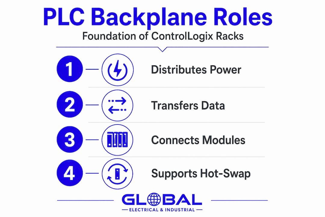
Backplane power distribution follows a daisy-chain design, meaning power travels from the supply through each connector position in sequence. High-resistance or degraded contacts anywhere along that chain cause a voltage drop that affects every module downstream. The failure mode is not always obvious. You may see a module go offline or show a connectivity fault without any explicit power alarm in the software.
Pro Tip: When maintaining legacy ControlLogix racks, inspect the backplane connector pins on both the chassis and the modules themselves. Oxidation, physical damage, or debris in the connector seats are the most common causes of intermittent module faults in systems that are five or more years old.
The power budget is the total current the power supply can deliver across all backplane rails, typically 5V DC and 24V DC. Every module in the chassis draws from this budget. If the combined draw of all installed modules exceeds the supply’s rated capacity, the system becomes unstable. This is not a theoretical concern. It is a hard electrical constraint that will cause real failures.
Redundancy architecture with multiple racks
Redundancy in ControlLogix is one of the most misunderstood topics in Allen-Bradley system design. The instinct for many engineers is to install a second controller in the same chassis as a backup. That approach is not supported and creates exactly the failure mode you are trying to prevent.
True ControlLogix redundancy requires three physically separate chassis. Here is how the architecture breaks down:
- Primary controller chassis: Contains the active controller module and redundancy module. This chassis runs the live program.
- Secondary controller chassis: Contains a matching controller and redundancy module. It mirrors the primary and takes over during a switchover event.
- I/O chassis: Contains all I/O and communication modules. Both controllers communicate with this chassis independently.
The reason for three chassis is straightforward. If both controllers share a backplane and that backplane develops a fault, you lose both controllers simultaneously. Separate chassis mean separate backplanes, which eliminates that single point of failure.
Supported redundancy also requires at least two ControlNet communication modules distributed across the chassis to maintain network health during switchovers. Continuity of network activity is required for the switchover to complete successfully.
Common redundancy mistakes to avoid during legacy system upgrades:
- Placing both controllers in one chassis to save panel space
- Using mismatched firmware versions between primary and secondary controllers
- Failing to account for the additional chassis power supplies in the panel layout
- Skipping the redundancy module (1756-RM) and expecting software-only failover
Pro Tip: Before committing to a redundancy retrofit on a legacy system, audit the existing chassis condition first. A degraded backplane in the primary chassis will undermine the entire redundancy architecture regardless of how correctly the software is configured.
Backplane power limits and troubleshooting faults
Power-related faults are the most common cause of unexpected module behavior in legacy ControlLogix systems, and they are routinely misdiagnosed as software or network issues. Understanding the numbers helps.
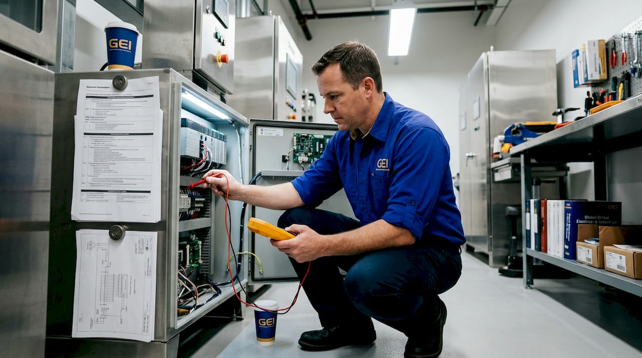
A real-world example makes this concrete. Adding a 1756-OW16I isolated relay output module to a 17-slot chassis caused the entire system to go offline. The root cause was the module’s backplane current draw of 210 to 250 mA, which pushed the chassis over its available power budget. The failure appeared as a connectivity loss rather than an explicit power fault, which led the technician to suspect a configuration error first.
Here is a reference table for common ControlLogix module backplane power draws:
| Module | 5V DC Draw | 24V DC Draw |
|---|---|---|
| 1756-L85E Controller | 2.9 A | 3.0 mA |
| 1756-IB16 Digital Input | 105 mA | 0 mA |
| 1756-OB16E Digital Output | 100 mA | 105 mA |
| 1756-OW16I Relay Output | 210-250 mA | 0 mA |
| 1756-EN2T EtherNet/IP Module | 400 mA | 0 mA |
When troubleshooting a module that won’t come online or a system that drops intermittently, work through these steps in order:
- Calculate the total backplane power draw for all installed modules and compare it against the power supply’s rated output
- Inspect the backplane connector seats in the chassis for debris, corrosion, or physical damage
- Reseat the affected module firmly and check for bent or damaged pins on the module connector
- Swap the suspect module into a known-good chassis slot to isolate whether the fault follows the module or stays with the slot
- Replace the power supply if voltage measurements at the backplane rails are below spec
Physical chassis condition and power delivery cause module connectivity failures more often than wiring or programming mistakes in legacy systems. That fact alone should change the order in which you troubleshoot.
Installation, expansion, and maintenance best practices
Getting a ControlLogix rack installed correctly from the start prevents most of the failures described above. The following practices apply whether you are commissioning a new system or retrofitting an existing one.
Module insertion and seating: Always insert modules straight and firm. A partially seated module will make intermittent backplane contact and produce faults that are difficult to reproduce. In legacy chassis that have had modules swapped many times, the connector seats can develop wear. Inspect them visually before insertion.
Slot planning for expansion: Leave at least two empty slots when designing a new rack layout. Adding modules later is common, and running a chassis to full capacity on day one means any expansion requires a new remote chassis. Studio 5000 Logix Designer integrates controller and I/O configuration, firmware updates, and diagnostics, so your slot layout should be documented in the project file from the beginning.
Pro Tip: When using Studio 5000 to configure a rack, set the module inhibit property on empty slots rather than leaving them unconfigured. This prevents the controller from generating nuisance faults when it scans slots expecting modules that aren’t there.
Additional maintenance practices worth building into your PM schedule:
- Inspect power supply output voltage quarterly on legacy systems, especially in high-temperature environments
- Clean chassis backplane connector areas with compressed air annually
- Document the power budget calculation and update it every time a module is added or replaced
- Verify firmware compatibility between the controller and all installed modules after any firmware update
Hot-swapping modules in a running legacy system requires care. Confirm the module type matches the configured slot in Studio 5000 before insertion. Inserting the wrong module type into a configured slot can cause the controller to fault the entire rack, not just the affected slot.
My take on Allen-Bradley rack challenges in legacy systems
I’ve worked through enough ControlLogix troubleshooting calls to have a strong opinion on where engineers lose time. The backplane gets underestimated almost every time. People treat it as passive infrastructure, the electrical equivalent of a mounting rail. It isn’t. It’s an active power distribution network with real constraints, and in a chassis that’s been in service for a decade, those constraints get tighter as connector quality degrades.
The redundancy misconception is the other one that costs real money. I’ve seen panels where a second controller was added to the primary chassis with genuine belief that this provided failover protection. It doesn’t. Redundancy must be designed as a system architecture solution, not just adding a second controller to one chassis. The documentation is clear on this, but it’s easy to miss if you’re working from tribal knowledge rather than the engineering spec.
What I’ve found actually works during retrofits is treating the power budget calculation as a mandatory deliverable before any module is ordered. Not a check at the end. A deliverable at the start. That one habit prevents the majority of post-installation surprises. Studio 5000 is a genuinely useful tool for diagnostics, but it can’t compensate for a chassis with worn connector seats or a power supply that’s operating at 95% of its rated capacity. The software tells you what the system thinks is happening. The physical inspection tells you what’s actually happening.
— Monica
Source Allen-Bradley rack components without the wait
When a legacy ControlLogix system needs a replacement chassis, power supply, or I/O module, lead times from the original manufacturer can stretch weeks or months. That’s not acceptable when a production line is down.

Industrialpartsusa stocks new, surplus, and remanufactured Allen-Bradley ControlLogix components, including chassis, power supplies, controller modules, and I/O modules, with same-day shipping on in-stock items. Every part goes through testing and inspection before it ships, and all items carry a one-year warranty backed by Industrialpartsusa directly. Whether you need a hard-to-find 1756 chassis for a retrofit or a replacement module to get a system back online today, Industrialpartsusa has the inventory and the technical background to support legacy Allen-Bradley systems at every stage.
FAQ
What is the backplane in an Allen-Bradley PLC rack?
The backplane is the circuit board at the rear of the chassis that simultaneously distributes DC power and carries the data communication bus between all installed modules. It is the electrical backbone of the entire rack system.
How many chassis does ControlLogix redundancy require?
True ControlLogix redundancy requires three separate chassis: one for the primary controller, one for the secondary controller, and one for I/O modules. Placing both controllers in a single chassis creates a shared backplane failure point and is not a supported configuration.
What causes a ControlLogix module to go offline unexpectedly?
The most common cause is insufficient backplane power delivery or degraded chassis connector integrity, not software or wiring faults. Always calculate the total module power draw and inspect backplane contacts before suspecting configuration errors.
Can you hot-swap modules in a ControlLogix rack?
Yes. Most ControlLogix modules support hot-swap while the system is powered, but the replacement module must match the type configured in Studio 5000 for that slot. Inserting the wrong module type can fault the controller for the entire rack.
How do you calculate the backplane power budget for a ControlLogix rack?
Add the 5V DC and 24V DC current draws for every module in the chassis using the module specifications from Rockwell Automation’s documentation. The total must not exceed the rated output of the installed power supply, with a safety margin recommended for legacy systems.
Recommended
- GE Emerson IC693CHS393 I/O Rack, Remote Expansion, 10 Slots – Global Electrical and Industrial
- GE Emerson IC693CHS399 I/O Rack – Remote Expansion, 5 Slots (700 ft.) – Series 90-30 – Global Electrical and Industrial
- GE Emerson IC693CHS392 I/O Rack Expansion – 10 Slots – Global Electrical and Industrial
- GE Emerson IC693CHS398 I/O Rack Expansion – 5 Slots – Series 90-30 – Global Electrical and Industrial