
What Is Motion Control? A Guide for Industrial Engineers
Motion control is one of those terms that sounds self-explanatory right up until you need to spec a system for a high-throughput assembly line. Most engineers assume what is motion control really means is “making things move.” The reality is far more precise. Motion control is a sub-field of automation that coordinates controllers, drives, and actuators to manage position, velocity, and acceleration with repeatable accuracy. In a semiconductor fab, a packaging line, or a CNC cell, that precision is what separates a functional machine from a profitable one. This guide breaks down the fundamentals, the technology stack, and the practical decisions that determine whether your motion system performs or fails.
Table of Contents
- Key takeaways
- What is motion control: core components and principles
- How motion control systems work in real time
- Types of motion control technologies and their applications
- Recent advances in motion control technology
- Implementation tips for engineers and technicians
- My take on what engineers consistently get wrong
- Source motion control components you can count on
- FAQ
Key takeaways
| Point | Details |
|---|---|
| Motion control is precision automation | It manages position, velocity, and acceleration in coordinated systems, not just mechanical movement. |
| Closed-loop feedback drives accuracy | PID-based control loops correct errors in real time, making feedback resolution and latency critical factors. |
| Technology type determines trade-offs | Electric servo, stepper, pneumatic, and hydraulic systems each suit different speed, accuracy, and cost requirements. |
| Mechanical integration is often the weak link | Inertia matching and gearbox ratios affect stability as much as controller software does. |
| AI and software simulation are reshaping the field | Modern motion control technology increasingly uses digital twins and adaptive algorithms to reduce commissioning time. |
What is motion control: core components and principles
At its core, a motion control system has four building blocks: the motion controller, the drive, the motor, and the feedback device. Understanding what each one does, and how they interact, is where most engineers build their mental model of the whole system.
The motion controller is the brain. It interprets high-level commands and translates them into precise, low-level signals that tell the drive what to do. In CNC machining, the controller reads G-code and performs real-time corrections to maintain micron-level repeatability. In a multi-axis robotic cell, it coordinates the timing of every joint simultaneously.
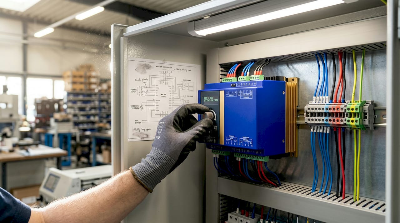
The drive (also called a servo drive or amplifier) takes the controller’s commands and converts them into the electrical current that powers the motor. Think of it as the translator between digital commands and physical torque. The drive also handles current regulation and, in modern systems, part of the feedback processing.
The motor is the actuator. Servo motors and stepper motors are the two dominant types in electric motion control:
- Servo motors use a closed-loop feedback mechanism to continuously correct position and speed. They handle dynamic loads well and are preferred for high-speed, high-precision applications.
- Stepper motors move in discrete increments and are typically run open-loop. They are simpler and cheaper, but they lose position if overloaded and lack the dynamic response of servos.
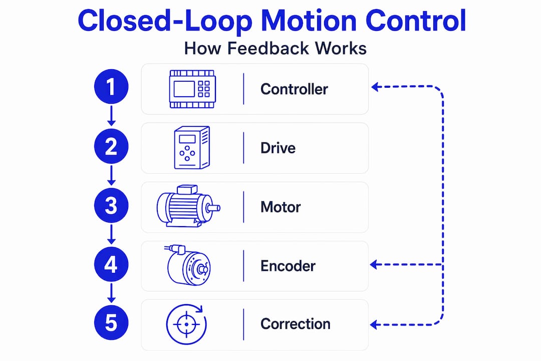
Feedback devices such as encoders and resolvers close the loop. An encoder mounted on the motor shaft reports actual position back to the controller, which compares it against the commanded position and issues a correction. This is the closed-loop control concept, and it is what separates precision motion from simple actuation.
The correction algorithm most commonly used is a PID controller: Proportional, Integral, Derivative. The proportional term reacts to current error, the integral term addresses accumulated error over time, and the derivative term anticipates future error based on the rate of change. Tuning these three gains correctly is one of the most consequential skills in motion control commissioning.
Pro Tip: Open-loop stepper systems are tempting because they eliminate feedback hardware costs, but if your application involves variable loads or requires position verification, the cost of a lost step or a missed position can far exceed the savings.
How motion control systems work in real time
The closed-loop cycle in a motion control system runs continuously, and the speed of that cycle determines how precisely the system can track a commanded trajectory. Servo update rates typically operate between tens and hundreds of kHz using PID algorithms for real-time correction. That means the controller is reading position feedback, calculating error, and issuing a correction thousands of times per second.
Here is the sequence of events in a single control loop cycle:
- The motion controller outputs a position or velocity command to the drive.
- The drive powers the motor to execute the command.
- The encoder reads the actual motor position and sends that data back to the controller.
- The controller calculates the difference between commanded and actual position (the error).
- The PID algorithm generates a correction signal.
- The drive applies the correction, and the cycle repeats.
The frequency at which this cycle runs directly affects tracking accuracy. A slow loop rate means the system is always reacting to errors that have already grown larger than necessary. A fast loop rate catches deviations early, before they compound.
Communication protocols are what make this speed possible across multi-axis systems. EtherCAT, for example, supports cycle times below 100 ms for deterministic performance across dozens of axes on a single network. PROFINET and EtherNet/IP are also widely used, though EtherCAT is the preferred choice when determinism and speed are non-negotiable.
One factor that engineers frequently underestimate is latency in the feedback path. Feedback loop resolution and latency critically affect system performance. A high-resolution encoder is only useful if the controller can process that data fast enough to act on it. If the feedback signal is delayed by even a few milliseconds due to network overhead or processing bottlenecks, the high resolution becomes meaningless. The true performance bottleneck is often the entire signal chain, not just the controller software.
In multi-axis systems, this challenge multiplies. Each axis must be synchronized, and any timing skew between axes introduces path errors. This is why deterministic protocols and coordinated motion planning algorithms are not optional features in precision automation. They are the foundation.
Types of motion control technologies and their applications
Motion control technologies span electrical, pneumatic, and hydraulic methods, and choosing the wrong one for your application creates problems that no amount of tuning will fix. Here is how they compare:
| Technology | Accuracy | Speed | Power density | Cost | Best fit |
|---|---|---|---|---|---|
| Electric servo | High | High | Medium | Medium-high | CNC, robotics, assembly |
| Stepper motor | Medium | Medium | Low | Low | 3D printing, light positioning |
| Pneumatic | Low | High | Medium | Low | Pick-and-place, clamping |
| Hydraulic | Low-medium | Medium | Very high | High | Heavy presses, construction |
Electric servo systems dominate precision industrial automation because they balance accuracy, speed, and durability better than the alternatives in most applications. Pneumatic systems are fast and cheap but offer limited position control. Hydraulic systems deliver enormous force but are difficult to control precisely and require significant infrastructure.
Within electric motion control, the choice between servo and stepper comes down to load dynamics and accuracy requirements. For a multi-axis motion control application like a robotic arm or a gantry system, servo motors are almost always the right answer. For a simple indexing table with predictable loads, a stepper system may be perfectly adequate.
One integration challenge that trips up even experienced engineers is inertia matching. The reflected inertia of the load, as seen through the gearbox, must be reasonably matched to the motor’s rotor inertia. Improper inertia matching leads to instability, oscillation, and premature drive or motor failure. The general rule of thumb is to keep the inertia ratio below 10:1, though tighter ratios are preferred for high-performance applications.
Pro Tip: When selecting a gearbox, do not just calculate the torque multiplication. Calculate the reflected inertia at the motor shaft. A high gear ratio reduces reflected inertia dramatically, which can mean the difference between a stable system and one that oscillates no matter how you tune the PID gains.
Recent advances in motion control technology
The field is moving fast, and several trends are changing how engineers design and commission motion systems.
- Software-defined simulation: Software-based testing tools now allow full machine simulation before physical hardware is commissioned. Engineers can validate motion profiles, detect collisions, and tune control parameters in a virtual environment, which cuts rework and shortens project timelines significantly.
- AI and vision integration: AI and 3D vision systems allow robots to adapt to unstructured environments. Instead of relying on fixed positions, adaptive motion systems can identify part variations and adjust trajectories in real time. This is transforming bin-picking, assembly verification, and quality inspection.
- Modular and open-architecture platforms: Open-architecture motion platforms allow third-party drives, motors, and controllers to interoperate, reducing vendor lock-in and giving engineers more flexibility in system design.
- Edge computing and predictive maintenance: Processing motion data at the edge, rather than sending it to a central server, reduces latency and enables real-time anomaly detection. Systems can flag bearing wear, encoder drift, or drive degradation before a failure occurs.
- Miniaturization: Drives and controllers are shrinking without sacrificing performance, enabling motion control integration in compact devices and collaborative robots that work alongside humans.
Implementation tips for engineers and technicians
Getting a motion control system right requires attention at every stage, from component selection through commissioning and long-term maintenance. Here are the most consequential decisions and pitfalls:
- Prioritize feedback path latency, not just resolution. A 23-bit encoder paired with a slow communication bus will underperform a 17-bit encoder on a fast, deterministic network. Match the feedback device to the control loop speed.
- Size your motor with margin. Continuous torque requirements and peak torque demands are different numbers. Sizing to continuous duty with no headroom for acceleration peaks is a common source of drive faults and thermal shutdowns.
- Tune the mechanical system before tuning the PID. If your system has resonance from a loose coupling or an undersized gearbox, no amount of gain adjustment will eliminate the oscillation. Fix the mechanics first.
- Use the right controller architecture for your axis count. A two-axis application and a twelve-axis coordinated gantry have fundamentally different controller requirements. A 2-axis motion module is appropriate for simpler systems, but complex coordinated motion demands a controller built for it.
- Document your tuning parameters. When a drive is replaced after a failure, having the original PID gains, feedforward values, and filter settings saves hours of recommissioning time.
Pro Tip: Before finalizing your motion system design, run a frequency response analysis on the mechanical load. Knowing the resonant frequency of your load lets you set derivative filters that prevent the PID loop from exciting that frequency, which is one of the most common causes of instability in servo systems.
My take on what engineers consistently get wrong
I have reviewed enough motion control projects to see the same failure patterns repeat across industries and machine types. The most persistent one is treating the controller as the system. Engineers spec a high-performance controller, pair it with a quality encoder, and then wonder why the system oscillates or fails to hold position under load.
What I have learned is that the mechanical integration is where most precision is lost. Couplings with backlash, gearboxes with high inertia ratios, and mounting structures with flex all degrade performance in ways that software cannot compensate for. The deterministic control loop is only as good as the mechanical chain it is trying to control.
The other thing I see consistently underestimated is the cost of latency. Engineers buy high-resolution encoders and feel confident about their feedback quality, but they do not audit the full signal path. Network overhead, controller scan time, and drive processing delay all add up. In a system running at 500 Hz loop rates, even a 2 ms delay is a significant fraction of the control period.
Looking ahead, I think software-defined motion control and AI-assisted tuning will change the role of the commissioning engineer more than any hardware advancement has. The engineers who thrive will be the ones who understand both the physics of the mechanical system and the logic of the software layer well enough to know when to trust the algorithm and when to override it.
— Monica
Source motion control components you can count on

When a motion control module fails on a production line, lead times from the OEM can stretch to weeks or months. Industrialpartsusa stocks a wide range of tested, ready-to-ship motion control hardware including servo drives, motion controllers, CPU modules, and multi-axis control cards from GE Fanuc, Allen-Bradley, and other major platforms. Every unit ships with a one-year warranty backed by in-house testing and repair capabilities. Whether you need a GE Fanuc CPU module for an existing automation cell or a hard-to-find legacy motion card, Industrialpartsusa carries the inventory to get your line back up fast. Visit Industrialpartsusa to search available stock and request same-day shipping on in-stock items.
FAQ
What is motion control in industrial automation?
Motion control is the coordinated management of position, velocity, and acceleration in automated systems using controllers, drives, motors, and feedback devices. It enables precise, repeatable movement in applications ranging from CNC machining to robotic assembly.
How does a closed-loop motion control system work?
The controller sends a command to the drive, the motor moves, and an encoder reports the actual position back to the controller. The controller calculates the error and issues a correction using a PID algorithm, repeating this cycle thousands of times per second.
What are the main types of motion control systems?
The primary types are electric servo, stepper motor, pneumatic, and hydraulic systems. Electric servo systems offer the best balance of accuracy and speed for most industrial applications, while pneumatic systems suit simple, fast actuation and hydraulic systems handle very high force requirements.
Why does feedback latency matter in motion control?
High-resolution feedback devices lose their advantage if the control loop cannot process the data fast enough. Latency in the signal chain prevents timely corrections, which degrades positioning accuracy and can cause instability at higher loop gains.
What communication protocols are used in motion control systems?
EtherCAT is the leading protocol for high-speed deterministic motion control, supporting cycle times below 100 ms across multi-axis networks. PROFINET and EtherNet/IP are also common, depending on the PLC platform and performance requirements of the application.
Recommended
- GE Emerson IC693DSM302 – 2 Axis Motion Control for Series 90-30 – Global Electrical and Industrial
- Global Electrical and Industrial – Your Partner in Automation
- GE Emerson IC693DSM314 4 AXIS Motion Control – Series 90-30 – Global Electrical and Industrial
- GE Fanuc IC693CPU340 Industrial Automation CPU Module – Global Electrical and Industrial