
How to Test Used Servo Motors Before Install
Dropping an untested used servo motor into a production line is one of the fastest ways to create unplanned downtime. When you test used servo motors before install, you catch winding faults, bearing wear, and encoder failures before they cost you hours of troubleshooting and potentially damage connected equipment. Used and surplus motors carry history you cannot see from the outside. A motor that looks clean can still have degraded insulation, a pitted bearing race, or a resolver signal that drifts under load. The testing procedures for servo motors covered here will give you a structured, shop-proven framework to verify every unit before it ever touches your machine.
Table of Contents
- Key Takeaways
- How to test used servo motors before install: preparation
- Electrical testing procedures
- Mechanical and feedback system tests
- Troubleshooting common issues found during testing
- Verifying test results and readiness for installation
- My take on testing before you install
- Get servo motors and parts that are already tested
- FAQ
Key Takeaways
| Point | Details |
|---|---|
| Visual inspection comes first | Check casing, shaft, connectors, and mounting points before connecting any power. |
| Electrical tests reveal hidden faults | Insulation resistance and winding resistance checks catch shorts and open circuits invisible to the eye. |
| Encoder testing prevents runaway events | Verify feedback signal integrity before powering the motor under load. |
| OEM drive pairing matters | Final functional tests should use the target drive to avoid false passes on compatibility. |
| Document everything | A test report protects you during installation and gives your maintenance team a baseline for future diagnostics. |
How to test used servo motors before install: preparation
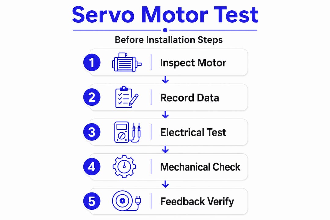
Before you run a single test, get organized. Rushing into electrical checks without the right tools or a clear record of the motor’s nameplate data is how technicians miss faults that show up six months later as production failures.
Essential tools and equipment
You will need the following for a thorough pre-installation servo motor inspection:
- Digital multimeter for winding resistance and continuity checks
- Megohmmeter (megger) rated for the motor’s voltage class, typically 500V or 1000V DC for most servo motors
- Servo tester or compatible drive for functional electrical performance checks
- Dial indicator or runout gauge for shaft runout measurement
- Oscilloscope or encoder tester to verify feedback signal quality
- Torque wrench and bearing listening tool (a screwdriver handle pressed to the housing works in a pinch)
- Personal protective equipment: insulated gloves, safety glasses, and arc flash rated PPE appropriate for the voltage levels involved
Pre-test documentation
Pull the motor’s nameplate data before touching a test lead. Record the rated voltage, current, winding resistance spec, encoder type, resolution, and frame size. This gives you a reference when you compare your measured values against acceptable ranges later.
Initial visual inspection should cover the motor casing for cracks or impact marks, shaft condition including any scoring or corrosion, connector pins for bending or oxidation, and mounting surfaces for stripped threads or deformation. Physical damage and loose connections are among the most common failure causes in used units, and they take about two minutes to find.
Pro Tip: Photograph every motor before testing. A timestamped image of the nameplate and any physical damage creates a clear record if a warranty dispute arises later.
Electrical testing procedures
Electrical tests are where most faults in used servo motors hide. Insulation resistance, winding resistance, and continuity checks are the three pillars of any credible used servo motor testing protocol.
Step-by-step electrical tests
-
Insulation resistance test (megger test): Disconnect all motor leads from the drive. Apply 500V DC between each motor phase lead and the motor frame (ground). A healthy servo motor should read above 100 megohms. A reading below 1 megohm indicates contaminated or degraded insulation and the motor should not be installed without refurbishment.
-
Winding resistance measurement: Using your multimeter in resistance mode, measure across each pair of motor phase leads: U to V, V to W, and W to U. Healthy windings show consistent resistance values between phases. Any reading that deviates more than 5% from the others, or an open circuit reading, signals a winding fault.
-
Continuity and short circuit check: Confirm continuity exists between each phase pair. Then check for shorts between each phase lead and the motor frame. Any continuity between a phase lead and ground confirms a winding short to ground, which is a condemn-level finding unless the motor goes to repair.
-
Functional electrical test with a servo tester or drive: Connect the motor to a compatible servo tester or drive with no mechanical load. Command a slow rotation in both directions. Observe current draw and listen for irregularities. This step validates that the motor responds to electrical commands correctly before mechanical load testing.
-
Check for drive versus motor faults: Structured testing using voltage measurements and wiring continuity separates motor faults from drive or cable issues. If the motor passes the megger and winding tests but fails the functional test, investigate the drive and cable before condemning the motor.
The comparison below shows what separates a pass from a fail on the core electrical checks:
| Test | Pass criteria | Fail indicator |
|---|---|---|
| Insulation resistance | Above 100 megohms to ground | Below 1 megohm |
| Winding resistance (phase to phase) | Within 5% across all three phases | Open circuit or more than 5% deviation |
| Ground continuity check | No continuity between phase and frame | Any continuity between phase and ground |
| Functional test current draw | Within nameplate rated current | Excessive draw or no response to command |
Pro Tip: Always allow the megohmmeter reading to stabilize for at least 60 seconds before recording. Early readings can give falsely optimistic numbers on marginally degraded insulation.
Mechanical and feedback system tests
Electrical integrity alone does not tell you whether a used servo motor will survive in a demanding cycle. Mechanical condition and feedback system accuracy determine whether the motor actually performs to spec under real operating conditions.
Bearing and shaft condition
Rotate the shaft slowly by hand. You are listening for grinding, clicking, or rough spots that indicate bearing wear or shaft runout. A smooth, consistent feel with no detectable lateral play is what you want. Mount a dial indicator against the shaft end and rotate it one full revolution. Runout exceeding the manufacturer’s tolerance (typically 0.001 to 0.002 inches for most precision servo motors) means the shaft is bent or the front bearing is damaged.
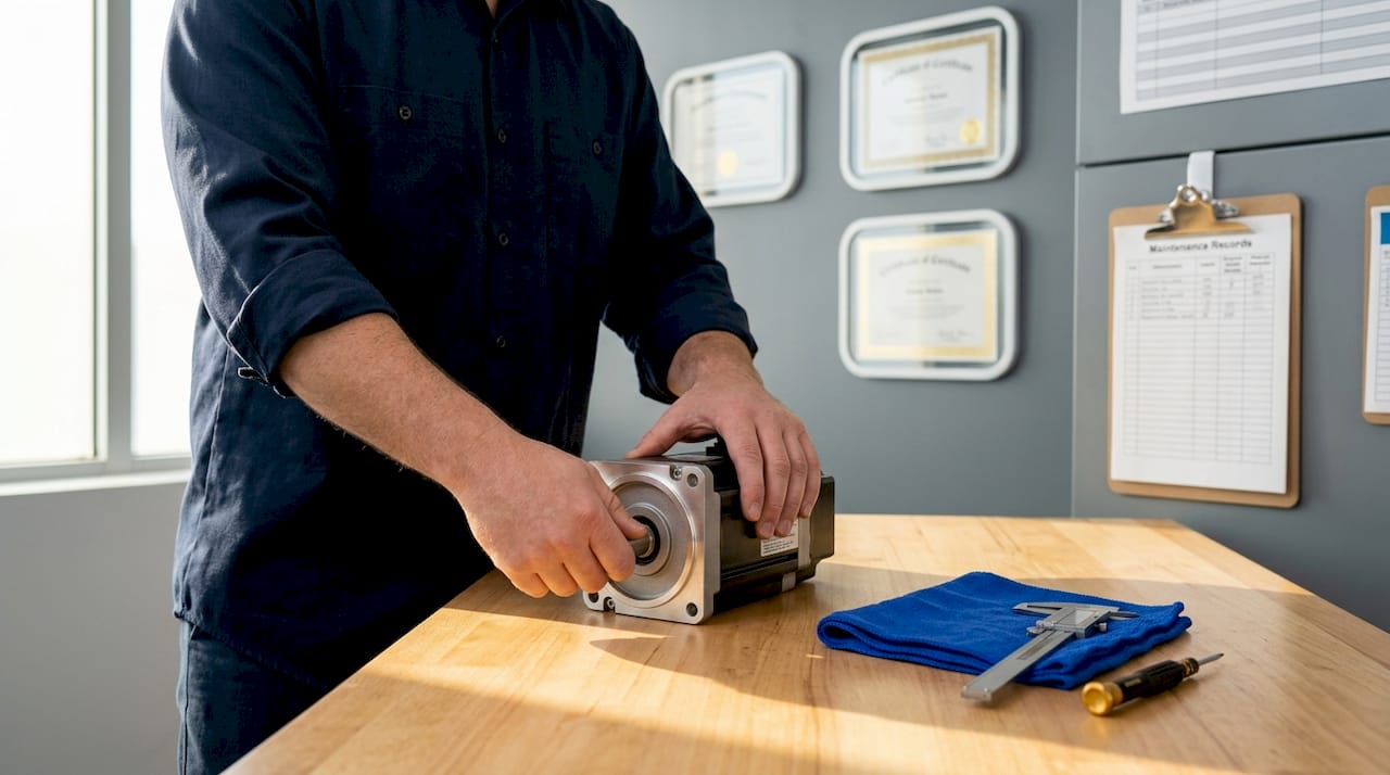
Excessive shaft runout or noisy bearings are not cosmetic issues. They accelerate coupling wear, cause vibration at the load, and can trigger false encoder counts if the encoder disc is mounted on the same shaft.
Encoder and resolver verification
Encoder and resolver failures cause some of the most dramatic servo failures in the field: full-speed runaway or complete loss of motion with an audible hum. Before installation, connect the encoder output to an oscilloscope or dedicated encoder tester and rotate the shaft by hand. Verify that:
- Channel A and Channel B produce clean quadrature square waves with no missing pulses
- The index pulse fires once per revolution at a consistent position
- Signal voltage levels match the encoder’s spec sheet
For resolvers, use a resolver test unit or the target drive’s diagnostic mode to confirm the sine/cosine output amplitudes are balanced and the phase relationship is correct.
Pro Tip: If you do not have an oscilloscope, most modern servo drives display encoder feedback counts in diagnostic mode. Rotate the shaft manually and watch the count increment cleanly. Jumps, skips, or frozen counts all point to encoder damage.
Mounting and alignment check
Inspect the motor’s mounting flange and pilot diameter for wear or out-of-round conditions. A deformed pilot diameter will cause misalignment even with a perfectly rebuilt motor, generating vibration and premature bearing failure in the application.
Troubleshooting common issues found during testing
Even with a good process, used servo motor testing surfaces problems that require interpretation. Here is how to read the most common findings:
-
Winding short to ground: Megger reading below 1 megohm with confirmed continuity between phase and frame. This motor needs rewinding or replacement. Do not install it.
-
Open circuit winding: Infinite resistance on one phase pair during winding resistance check. Could be a broken lead wire inside the terminal box or an actual winding break. Check terminal connections first before condemning the motor.
-
Noisy or rough bearings: Detected during manual shaft rotation. Bearing measurement and shaft runout are standard checks in any credible refurbishment process. A motor with confirmed bearing noise needs bearing replacement before installation.
-
Encoder signal anomalies: Missing pulses, erratic counts, or channel cross-talk detected during encoder testing. Some encoder failures are connector related. Reseat connectors and retest before assuming the encoder disc or read head is damaged.
-
Excessive current draw during functional test: If current exceeds nameplate rating during a no-load spin test, suspect a shorted turn within a winding or a mechanical binding issue. Run the megger test again under warm conditions to check if the insulation reading changes with temperature.
Avoid the common mistake of skipping voltage spec verification before the functional test. Running a 200V rated motor on a 400V drive even briefly can destroy the insulation you just verified as good. Always confirm the drive output voltage matches the motor’s rated voltage before powering up.
When testing reveals multiple failure modes or marginal readings, professional refurbishment is the right call. Systematic fault elimination through structured testing keeps downtime lower than guessing and replacing.
Verifying test results and readiness for installation
Once all tests are complete, consolidate your findings into a simple test report before the motor goes to the installation team. This record protects you and your maintenance department for the life of the equipment.
Your pre-installation servo motor inspection report should confirm:
- Insulation resistance value (megohms) and date of test
- Phase-to-phase winding resistance readings for all three pairs
- Shaft runout measurement and bearing condition assessment
- Encoder or resolver signal verification result
- No-load functional test current draw versus nameplate rating
- Confirmation that motor voltage, current, and frame specs match the target application
Final acceptance testing using the factory-specific drive reduces rework and confirms true operational compatibility. A motor that passes bench electrical tests but has never been spun with the actual drive profile it will see in production can still produce surprises. If at all possible, run the motor on the target drive, or at minimum a drive of the same model and firmware version, before committing to installation.
Check that the encoder calibration status is documented, especially for absolute encoders that hold a home position reference. Losing that reference data during installation will require re-homing the axis, which costs time on a live machine.
My take on testing before you install
I’ve watched technicians skip the megger test on a “visually perfect” used servo motor and have it fail within two weeks of installation, taking out a drive in the process. The cost of that failure was about forty times what a ten-minute insulation resistance check would have taken. That is not an edge case. It happens regularly when teams are under schedule pressure.
What I’ve learned from working through these situations is that the electrical and mechanical tests are not separate checklists. They are one integrated picture. A motor with borderline insulation resistance and a slightly noisy bearing is not “almost fine.” It is a motor that will fail at the worst possible time, under heat and load, when the production line is running full speed.
The part that most articles get wrong is the OEM drive pairing point. I’ve seen motors pass generic bench tests and then behave erratically when paired with the specific drive model they were designed for. Testing with the factory-specific drive is not optional for critical axes. It is the only way to be confident you are not creating a compatibility problem that only shows up under closed-loop control.
Document every test. Not for compliance, but because six months from now when that motor starts showing intermittent faults, the baseline reading you took today is worth more than any amount of on-the-fly troubleshooting. A single page test report is the cheapest insurance in the shop.
— Monica
Get servo motors and parts that are already tested

Industrialpartsusa stocks new, surplus, and remanufactured servo motors along with the automation parts that support them, including GE Fanuc I/O modules and control system modules commonly integrated with servo-driven axes. Every unit goes through cleaning, inspection, and testing before it ships, and each comes backed by a one-year warranty. If you need a part fast, same-day shipping is available on in-stock items. For motors that need bench diagnostics or repair before you can put them back in service, the team at Industrialpartsusa handles that too. Contact them directly to discuss your servo motor requirements and get a unit that is ready to install.
FAQ
What tests should I run on a used servo motor before installing it?
Run an insulation resistance test (megger), phase-to-phase winding resistance checks, an encoder or resolver signal verification, a manual shaft rotation check for bearing condition, and a no-load functional spin test on a compatible drive. This combination covers the electrical, mechanical, and feedback failure modes most common in used units.
What insulation resistance reading means a servo motor is safe to install?
A reading above 100 megohms between any motor lead and the motor frame indicates acceptable insulation. Any reading below 1 megohm means the motor should not be installed without refurbishment or rewinding.
How do I tell if a servo motor’s encoder is working correctly?
Connect the encoder output to an oscilloscope or encoder tester and rotate the shaft by hand. Clean quadrature square waves on channels A and B, a consistent index pulse once per revolution, and correct signal voltage levels all confirm a functional encoder. Missing pulses or erratic counts indicate damage.
Why does the choice of drive matter for pre-installation testing?
Testing with the target drive catches compatibility issues that generic bench tests miss. A motor may pass electrical checks but behave incorrectly under closed-loop control with a specific drive profile, producing faults that only appear during actual operation.
When should a used servo motor go to professional repair instead of being installed?
Send the motor to repair if insulation resistance tests below 1 megohm, winding resistance shows an open circuit or more than 5% phase imbalance, bearing noise is confirmed during manual rotation, or multiple failure modes are found during testing. Installing a marginally failing motor under schedule pressure is always more expensive than repairing it first.
Recommended
- GE Emerson IC693ACC300 – 16 Point Input Simulator Module | Series 90-30 – Global Electrical and Industrial
- GE Fanuc IC693CPU374 Industrial Automation CPU Module – Global Electrical and Industrial
- GE Fanuc IC693CPU351 Series 90-30 CPU Controller Module – Global Electrical and Industrial
- GE Fanuc IC693CPU341 Industrial Automation Control System Module – Global Electrical and Industrial