
How Conveyor Systems Are Controlled: Engineer’s Guide
Most engineers and operations managers know their conveyor systems move product from point A to point B. Far fewer fully understand how conveyor systems are controlled at the component level, and that gap is where unplanned downtime, sorting errors, and safety incidents originate. Modern conveyor control is a layered architecture: PLCs executing motor sequences, VFDs managing speed, sensors feeding real-time position data, and safety interlocks operating independently of all of it. Understanding each layer is the difference between a line you react to and a line you command.
Table of Contents
- Key takeaways
- How conveyor systems are controlled: core components
- Conveyor system control methods and automation techniques
- Safety integration and maintenance control
- Practical challenges in conveyor control design
- My take on conveyor control after years in the field
- Find the right parts for your conveyor control system
- FAQ
Key takeaways
| Point | Details |
|---|---|
| PLCs are the system brain | PLCs execute ladder logic to manage motor sequences, sensor feedback, and safety interlocks on conveyor lines. |
| VFDs reduce mechanical stress | Variable Frequency Drives ramp motor speed smoothly, cutting wear on belts, gearboxes, and couplings. |
| Safety must be hard-wired | Emergency stops and safety relays must operate independently of PLC logic to meet compliance standards. |
| Purge logic prevents pile-ups | Multi-conveyor systems need programmed purge sequences to clear downstream material before motors stop. |
| Sensor scan times matter | Tuning sensor-PLC communication scan rates is as critical as motor speed for accurate sorting and counting. |
How conveyor systems are controlled: core components
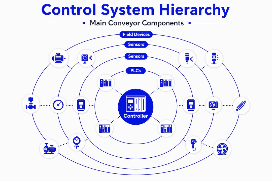
The architecture behind conveyor system control is best understood as a hierarchy. At the top sits the controller. Below it are the drive and motor hardware. Below that are the sensors and field devices that feed the controller real-time data. Each layer depends on the one above it for commands and the one below for feedback.
PLCs: the system brain
PLCs execute motor sequences using ladder logic programs that monitor inputs from sensors and switches, then trigger outputs to motors, solenoids, and alarms. On a typical conveyor line, the PLC manages start and stop sequencing, tracks zone occupancy, handles fault states, and communicates with higher-level systems like SCADA or MES platforms. A GE Fanuc Series 90-30, for example, can handle dozens of I/O points and execute scan cycles fast enough to track product movement across multiple belt segments simultaneously.
VFDs: speed and torque management
VFD speed ramping is one of the most underutilized tools in conveyor system automation. Rather than starting a motor at full voltage, a VFD accelerates it over a programmable ramp time, dramatically reducing inrush current and mechanical shock. The same controlled deceleration happens at stop. On high-throughput lines running heavy loads, this directly translates to longer belt life and fewer gearbox replacements.
Sensors and field devices
The PLC is only as smart as the data it receives. Photo eyes detect product presence at zone boundaries. Proximity sensors confirm gate positions and belt tension. Encoders on drive rollers measure actual belt velocity and can detect slip. Together, these devices give the PLC a continuous picture of what is happening on the belt, not just what the program assumes is happening.
Here are the primary sensor types used in conveyor control:
- Photo eyes (through-beam and diffuse): Product detection at zone entry and exit points
- Inductive proximity sensors: Metal target detection for mechanical position confirmation
- Rotary encoders: Belt speed and distance measurement for position tracking
- Temperature sensors: Motor and gearbox thermal monitoring for early fault detection
- Belt misalignment switches: Lateral drift detection to prevent belt edge damage
Control panels and HMIs
Control panels must prioritize reliability, user clarity, and safety integration. Clean wiring with consistent labeling, proper grounding, and segregated signal and power wiring are not cosmetic choices. They directly affect how fast a technician can diagnose a fault and get the line back up. HMIs sit on top of the control panel interface, giving operators a visual view of conveyor status, alarm history, and manual override capability without needing to open a panel door.
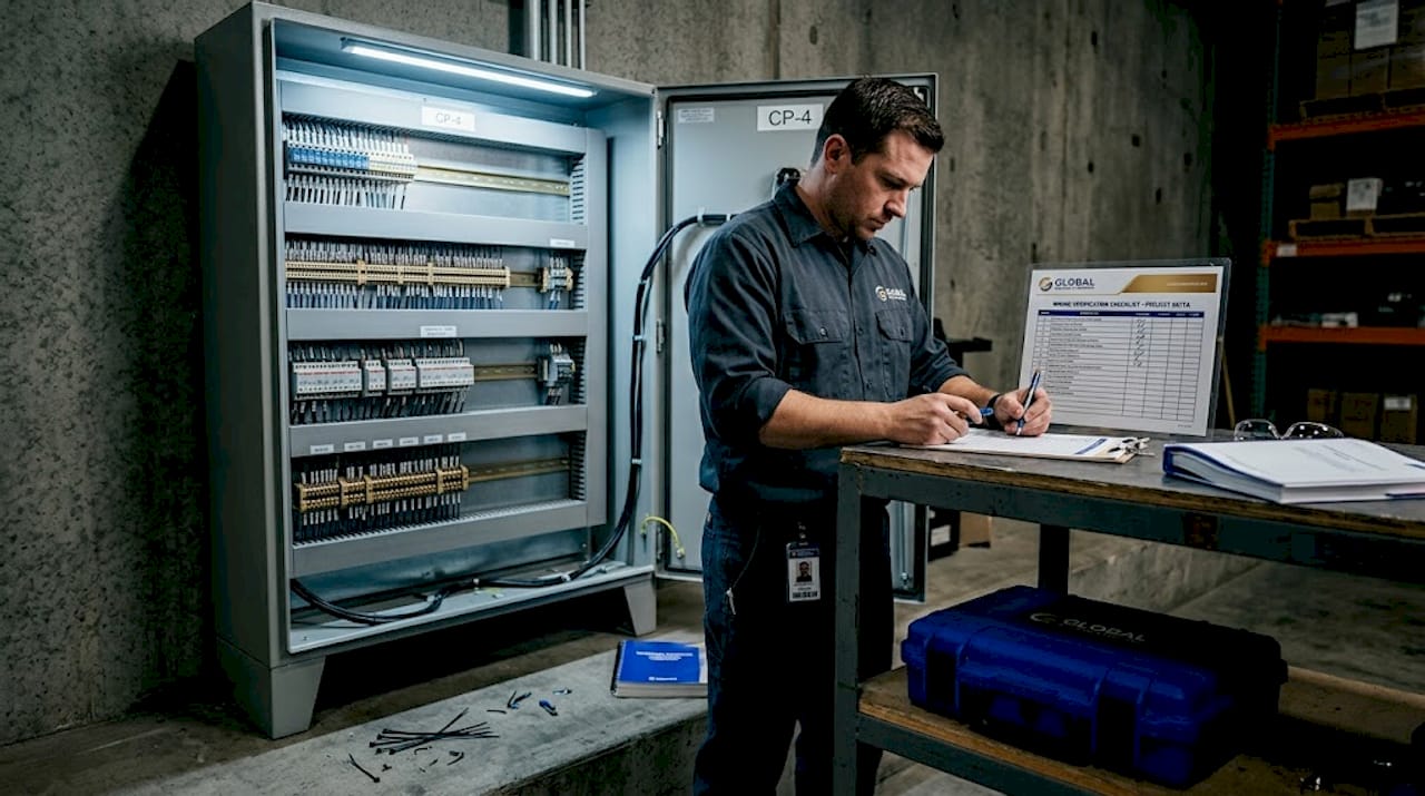
Pro Tip: Label every wire at both termination points using the same identifier. When troubleshooting a fault at 2 a.m., that labeling convention will save your technician 20 minutes per fault.
Conveyor system control methods and automation techniques
Understanding the types of conveyor controls goes beyond knowing what hardware is present. The logic programmed into the PLC determines how the system behaves under every condition, normal and abnormal.
The most common conveyor control methods, in order of operational complexity, work like this:
-
Simple start/stop sequencing. The PLC monitors a run permissive (all safety circuits closed, no faults active) and energizes the motor contactor. On shutdown, it sequences motors off in reverse order to prevent material from backing up on a stopped belt.
-
Zone-based accumulation control. Each belt segment activates only when a sensor confirms product is present or approaching. This saves energy on lightly loaded lines and prevents product collisions in accumulation zones. The PLC monitors zone sensors and controls individual zone motors independently.
-
Speed control via VFD. Rather than running at a fixed speed, the PLC sends a speed reference signal to the VFD based on production demand or downstream buffer levels. This is common in systems feeding packaging machines that run at variable rates.
-
Sorting and diverting logic. When a barcode scanner or vision system identifies a product, the PLC records its position and triggers a divert gate or pusher when that product arrives at the correct location. The timing calculation accounts for belt speed and the distance from the read point to the divert.
-
Multi-conveyor synchronization. On lines with multiple belt segments running at different speeds, the PLC coordinates handoff speeds to prevent product gaps or pile-ups at transfer points. Encoder feedback from each drive confirms actual speed rather than relying on commanded values.
-
Automated fault response. When a sensor detects a jam, a belt drift switch trips, or a motor thermal overload opens, the PLC executes a pre-programmed fault response: stopping affected zones, logging the fault with a timestamp, and alerting the operator via the HMI or plant floor annunciator.
The real efficiency gains in conveyor system automation come from combining these methods intelligently. A line that uses zone control, speed modulation, and predictive fault logic simultaneously will consistently outperform one that only uses simple start/stop control.
Safety integration and maintenance control
Safety in conveyor control is not a feature of the PLC program. It is a separate, parallel system that the PLC cannot override. This distinction matters enormously for both compliance and real-world reliability.
E-stops and safety relays must be hard-wired and independent of PLC logic. If the PLC crashes, hangs, or outputs a wrong state during a software fault, the safety circuit must still function. This is why safety-rated relays with force-guided contacts and monitored reset functions are mandatory on any guarded conveyor, not optional add-ons.
Beyond emergency stops, here are the safety and monitoring controls that directly affect uptime:
- Belt drift switches: 42% market revenue share held by major alignment switch manufacturers signals how widely these are deployed. A belt that tracks off center destroys edge seals and can pull away from drive rollers entirely.
- Pull-cord switches: Mounted along the belt length, these allow any worker near the conveyor to stop it immediately from any point.
- Zero-speed switches: Detect when a belt has stopped while the drive is still energized, indicating a broken belt or severe jam before the motor overheats.
- Thermal overload relays: Protect motors from sustained overcurrent conditions caused by mechanical binding or overloading.
Proactive conveyor assessments along the entire belt length, not just at the drive and tail pulleys, are what separate lines with predictable uptime from lines that fail at random. Spot-checking only the motor end is a false economy.
Weekly inspections reduce failure costs substantially by catching belt wear, material buildup on return rollers, and misalignment before they become unplanned stops. Schedule inspection routes that cover every idler, every belt cleaner, every sensor bracket, and every cable entry point.
Pro Tip: Build a digital inspection checklist tied to your CMMS. When a technician flags a borderline belt splice or a worn cleaner blade, that record creates a maintenance trigger before the next failure, not after.
AI-enabled monitoring systems are now capable of predicting motor bearing failures, belt degradation, and misalignment events from vibration and thermal signature analysis, pushing conveyor belt control technology toward fully predictive operation rather than reactive repair.
Practical challenges in conveyor control design
Even well-designed systems underperform when certain programming and design details are overlooked. The challenges below are the ones most commonly responsible for the gap between a system’s designed capacity and its actual throughput.
| Challenge | Common Mistake | Better Approach |
|---|---|---|
| Purge logic in multi-belt lines | Stopping all conveyors simultaneously on shutdown | Program downstream purge sequences to clear material before motors stop |
| Sensor scan time tuning | Assuming motor speed optimization is sufficient | Align PLC scan cycle with sensor response time to prevent missed counts |
| Installation variability | Using default PLC parameters from commissioning templates | Tune acceleration, deceleration, and detection windows to actual belt length and load |
| Zone sensor placement | Positioning sensors based on mechanical convenience | Place sensors to give the PLC maximum time to respond before a product reaches the next zone boundary |
| Custom PLC programming | Using generic ladder logic not adapted to plant workflow | Write control logic that reflects actual product flow, buffer sizes, and downstream machine states |
Purge logic is critical in any system where multiple conveyors feed into each other. When an upstream motor stops while downstream belts are still loaded, material continues to arrive at a stationary transfer point. The result is a mechanical jam that stops the entire line and risks belt and roller damage.
Sensor-PLC communication latency causes sorting errors and missed counts even when motor speed is perfectly dialed in. If the PLC scan cycle is 20ms but the sensor pulse from a fast-moving product lasts only 10ms, the controller will miss detections. Reducing scan time or using interrupt-driven I/O modules solves this, but it requires deliberate configuration during commissioning.
My take on conveyor control after years in the field
I’ve watched operations teams spend serious money on new conveyor hardware and still end up with the same downtime problems they had before. The hardware almost never is the root cause. The issue is almost always the control logic, the sensor configuration, or the maintenance approach around the system.
What I’ve found actually works is investing in the programming side at least as heavily as the mechanical side. A thoughtfully written PLC program with proper purge logic, zone sequencing, and fault handling will outperform generic OEM control software on custom plant layouts every time. The GE Fanuc Series 90-30 platforms I’ve seen running conveyor lines for 20 years are not performing well because the hardware is miraculous. They perform well because someone took the time to write control logic that fits that specific line’s behavior.
The other shift I think is genuinely worth the investment is predictive monitoring. Not because it is trendy, but because the data is there. Vibration, thermal, and current draw signatures tell you a bearing is failing weeks before it seizes. Ignoring that data in favor of scheduled replacement intervals is leaving money on the table.
Custom control solutions and proactive diagnostics are not luxuries for large operations. They are the baseline for any line where downtime costs real money.
— Monica
Find the right parts for your conveyor control system
When a PLC module, VFD, or I/O card fails on a conveyor control system, lead time from the OEM is often measured in weeks. For legacy platforms still running production lines, that wait is simply not an option.

Industrialpartsusa stocks new, surplus, and remanufactured automation components, with a particular focus on the GE Fanuc, Allen-Bradley, and Omron platforms that power thousands of active conveyor systems worldwide. Every part ships with a one-year warranty and same-day shipping on in-stock inventory. If your facility is running legacy controls and needs reliable sourcing for hard-to-find modules, the automation parts catalog covers the components most likely to be on your critical spares list. For teams evaluating sourcing options beyond a single supplier, the guide to obsolete PLC part alternatives is worth a read before your next emergency sourcing call.
FAQ
What controls a conveyor system?
A conveyor system is primarily controlled by a Programmable Logic Controller (PLC), which executes motor sequences and processes sensor inputs. Supporting hardware includes Variable Frequency Drives for speed control, HMIs for operator interaction, and hard-wired safety relays that operate independently of the PLC.
How are conveyors operated in automated manufacturing?
In automated settings, conveyors are operated through PLC programs that manage zone activation, speed modulation via VFDs, and sorting logic triggered by sensor or scanner input. Operators interact through HMIs and can override individual zones without interrupting the full line.
What is purge logic in a conveyor control system?
Purge logic is a PLC-programmed shutdown sequence that keeps downstream conveyors running long enough to clear any material on the belt before stopping the motor. Without it, multi-conveyor systems risk mechanical jams and belt damage at transfer points every time the line shuts down.
How do VFDs improve conveyor belt control?
VFDs allow the PLC to ramp motor speed up and down gradually rather than switching full voltage on and off. This reduces mechanical shock on belts, gearboxes, and couplings, lowers energy consumption at partial loads, and extends the service life of drive components significantly.
Why do sensor scan times affect conveyor system performance?
If the PLC scan cycle is slower than the duration of a sensor pulse from a fast-moving product, the controller will miss that detection entirely. Tuning scan times to match actual product speed and sensor response is a commissioning step that directly determines sorting accuracy and count reliability.