
How Servo Drives Receive Position Feedback Explained
Understanding how servo drives receive position feedback is the difference between a motion control system that holds tight tolerances and one that drifts, overshoots, or fails without warning. Every servo drive depends on a continuous stream of position data from a sensor to know where the motor shaft actually is, compare it to where it should be, and correct the error in real time. This article breaks down the sensor types that supply that data, the internal processing chain that converts raw signals into motor commands, and the calibration practices that keep everything accurate on the plant floor.
Table of Contents
- Key takeaways
- How servo drives receive position feedback: the core concept
- Sensor types used in servo feedback systems
- Internal processing: what the drive does with feedback data
- Signal and data flow from sensor to motor actuation
- Calibration, error sources, and troubleshooting
- My take on where servo feedback is heading
- Servo drive components from Industrialpartsusa
- FAQ
Key takeaways
| Point | Details |
|---|---|
| Feedback is non-negotiable | Servo drives operate as closed-loop systems; without position feedback, precise motion control is impossible. |
| Sensor choice shapes performance | Encoders, resolvers, and potentiometers each suit different environments and resolution requirements. |
| DSP loops run fast | Drives process feedback and correct errors at 8 to 32 kHz, making loop speed a key performance factor. |
| Calibration prevents drift | Offset bias in the summing junction must be zeroed at initialization to eliminate steady-state position error. |
| Signal quality determines accuracy | Noise, resolution limits, and interface type all affect how cleanly feedback reaches the drive’s processor. |
How servo drives receive position feedback: the core concept
Before getting into hardware specifics, it helps to understand what “receiving feedback” actually means inside a drive. A servo drive does not simply send power to a motor and hope for the best. It continuously compares the commanded position from the controller to the actual position reported by a sensor. The gap between those two values is the error signal, and the drive’s entire job is to reduce that error to zero as fast as possible.
Position feedback systems provide the real-time data that makes this loop possible. Without that data, the drive is operating open-loop, which is fine for simple speed control but completely inadequate for positioning applications in CNC machining, robotics, or packaging automation.
Sensor types used in servo feedback systems
The sensor attached to the motor shaft is where position data originates. Three technologies dominate industrial servo applications, and each has a clear use case.
Encoders
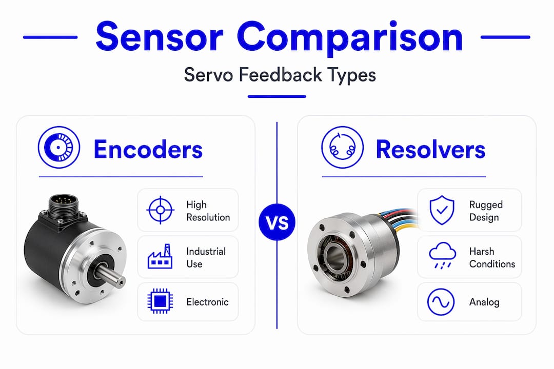
Encoders are the most common feedback device in modern industrial servo systems. Incremental encoders generate a pulse train as the shaft rotates, and the drive counts those pulses to track relative position. Absolute encoders output a unique digital word for every shaft position, so the drive knows exact position even after a power cycle without needing a homing routine.
Encoders typically offer 1,000 to 10,000 counts per revolution, with high-end models reaching 23-bit resolution or beyond. That level of granularity is what allows a servo to hold position to fractions of a degree in a semiconductor pick-and-place machine or a servo-driven press.
Resolvers
Resolvers are the rugged choice. They are transformer-based devices with no active electronics, which means they can tolerate environments that would destroy an encoder. Resolvers withstand temperatures up to 200°C and handle vibration levels common in heavy industrial and aerospace settings. The trade-off is that the drive needs a resolver-to-digital converter (RDC) to translate the analog sine/cosine output into usable position data, which adds a processing step.
Potentiometers and external magnetic encoders
Potentiometers appear in lower-cost RC-style servos and some legacy industrial systems. They provide a simple analog voltage proportional to shaft angle, which the drive reads through an ADC. Resolution is limited, and they wear mechanically over time. For applications where you need more precision without replacing the entire servo, external magnetic encoders like the AS5600 offer 12-bit resolution and can be retrofitted to existing motors to enable tighter closed-loop control.
Sensor comparison at a glance
| Sensor type | Resolution | Environment tolerance | Typical use case |
|---|---|---|---|
| Incremental encoder | 1,000–10,000+ CPR | Moderate | CNC, robotics, conveyors |
| Absolute encoder | Up to 23-bit | Moderate | Multi-axis, no-homing systems |
| Resolver | Moderate (12-bit equiv.) | High (up to 200°C) | Heavy industry, aerospace |
| Potentiometer | Low | Low | RC servos, legacy systems |
| Magnetic encoder (external) | 12-bit | Moderate | Retrofit, custom controls |
Internal processing: what the drive does with feedback data
Once the sensor sends its signal to the drive, the real work begins. The drive’s digital signal processor (DSP) sits at the center of this process, running the position control loop continuously.

The summing junction inside the DSP subtracts the actual position value from the commanded position value every single cycle. Servo drives execute this subtraction at 8 to 32 kHz, meaning the error is recalculated thousands of times per second. That speed is what allows a servo to respond to disturbances, load changes, and command updates with the responsiveness that industrial automation demands.
The resulting error value feeds into the PID controller. The proportional gain (Kp) determines how aggressively the drive responds to position error. The integral gain (Ki) accumulates error over time and eliminates the steady-state offset that pure proportional control always leaves behind. The derivative gain (Kd) looks at the rate of change of error and dampens oscillation before it becomes overshoot. PID tuning iterates through these three gains, typically starting with Kp, then adding Ki, then Kd.
Pro Tip: When tuning a servo loop for the first time, set Ki and Kd to zero and increase Kp until the motor just starts to oscillate, then back off 20 to 30 percent. That gives you a stable proportional baseline before you introduce integral and derivative action.
Feedback signal quality directly affects how well the PID controller can do its job. A noisy or low-resolution signal creates a floor of uncertainty that no amount of PID tuning can eliminate. The drive cannot correct for an error it cannot measure.
Signal and data flow from sensor to motor actuation
Understanding position feedback in servo drives also means tracing the full path a signal takes from the sensor to the point where the motor actually moves.
The path looks like this:
- The sensor generates a raw signal: analog voltage from a potentiometer or resolver, quadrature pulses from an incremental encoder, or a serial digital word from an absolute encoder using protocols like SSI, BiSS-C, or EnDat.
- The drive’s feedback interface conditions and digitizes that signal. Resolver signals pass through an RDC. Encoder pulses feed into a hardware counter. Digital protocols are decoded by the DSP directly.
- The DSP compares the digitized position to the command from the motion controller. Feedback signals range from analog voltages to digital protocols like EtherCAT and SPI, depending on the drive’s interface architecture.
- The PID output becomes a current command, which the current loop and amplifier convert into actual phase currents through the motor windings.
- The motor generates torque, the shaft moves, and the sensor reports the new position, restarting the cycle.
The current loop operates faster than the position loop. Amplifier current bandwidth must be at least five times the velocity loop bandwidth to maintain stability, which is why servo amplifiers are designed with significantly higher current loop rates than the position loop rates the user typically configures.
Communication between the servo drive and the upstream motion controller adds another layer. Step/direction interfaces are common in simpler systems. Industrial networks like EtherCAT, PROFINET, and CANopen carry both command data and feedback data over a single cable in more sophisticated architectures. Motion control integration with absolute encoders and synchronous motors over these networks is a growing standard in smart manufacturing.
Calibration, error sources, and troubleshooting
Getting the hardware right is only part of the job. Feedback accuracy depends heavily on how the system is configured and maintained.
-
Calibrate the feedback offset at initialization. The summing junction must start from a known zero. Any offset bias in the feedback calculation directly causes a steady-state position error that persists regardless of PID tuning. Offset calibration at drive power-up is not optional in precision applications.
-
Identify and eliminate signal noise. Long encoder cable runs, unshielded wiring near VFD output cables, and ground loops are the most common noise sources in industrial installations. Use differential signal wiring, proper cable shielding tied to ground at one end, and physical separation from power cables.
-
Match feedback resolution to your accuracy requirement. A 1,000-count encoder on a 5 mm pitch ball screw gives you 5 microns per count. If your tolerance is tighter than that, the encoder is the limiting factor, not the drive or the PID gains.
-
Check for intermittent faults before replacing hardware. A servo fault that appears randomly and clears on power cycle is often a connector with high contact resistance or a cable with an intermittent break. Pull and reseat all feedback connectors before condemning the encoder or the drive.
-
Verify sensor alignment after any mechanical work. Encoder couplings that slip, resolvers that shift angular position, and potentiometers that rotate on their mounting all introduce a fixed offset error that looks exactly like a calibration problem.
Pro Tip: If a servo is holding position but with a consistent offset you cannot tune out, measure the raw feedback signal at the drive’s diagnostic port before adjusting PID gains. The problem is almost always in the sensor or wiring, not the control loop.
My take on where servo feedback is heading
I’ve spent years watching engineers treat feedback calibration as a one-time setup task, and it consistently creates problems down the line. Thermal drift, mechanical wear, and connector oxidation all shift feedback accuracy gradually. The systems that stay accurate are the ones where calibration is treated as a periodic maintenance item, not a commissioning checkbox.
What I find genuinely interesting right now is the shift toward integrated feedback. Motor manufacturers are embedding multi-turn absolute encoders directly into the motor housing, eliminating the separate coupling and the mechanical alignment issues that come with it. Combined with smarter DSPs that can detect encoder health in real time, these systems are starting to support predictive maintenance by flagging degrading feedback signal quality before a fault occurs.
The engineers I’ve seen get the best results from their servo systems are the ones who understand that feedback quality is the ceiling on everything else. You can have the best drive on the market, but if your feedback signal is noisy or miscalibrated, you are leaving performance on the table. My top advice: invest in feedback resolution and signal integrity first, then tune the loop.
— Monica
Servo drive components from Industrialpartsusa

If you are sourcing servo drives, feedback interface modules, or motion controllers for an existing automation system, Industrialpartsusa stocks a wide range of new, surplus, and remanufactured components ready to ship. Their inventory includes servo interface modules like the GE Emerson IC693MCM001 for Series 90-30 systems, along with CPU modules and Genius I/O components that integrate directly with servo feedback architectures. Whether you are maintaining a legacy GE Fanuc system or building out a new motion control cell, Industrialpartsusa carries the parts you need with same-day shipping on in-stock items and a one-year warranty backed by in-house testing and repair.
FAQ
What sensors do servo drives use for position feedback?
Servo drives most commonly use incremental encoders, absolute encoders, and resolvers. Encoders offer high resolution (up to 23-bit), while resolvers are preferred in high-temperature or high-vibration environments.
How fast does a servo drive process position feedback?
Servo drives process feedback at 8 to 32 kHz, recalculating the position error thousands of times per second to maintain tight control over motor position.
What causes steady-state position error in a servo system?
Steady-state error is most often caused by an uncalibrated feedback offset at the summing junction, insufficient integral gain in the PID controller, or a feedback signal with too little resolution for the required positioning accuracy.
How do servo drives communicate feedback data to a motion controller?
Servo drives exchange position data with motion controllers through interfaces like EtherCAT, PROFINET, CANopen, or simple step/direction signals, depending on the system architecture and the controller’s supported protocols.
Can you improve servo feedback without replacing the motor?
Yes. Adding an external magnetic encoder like the AS5600 to an existing motor shaft provides 12-bit resolution and enables tighter closed-loop control without a full motor replacement.
Recommended
- GE Emerson IC693ACC300 – 16 Point Input Simulator Module | Series 90-30 – Global Electrical and Industrial
- GE Emerson IC693MCM001 Digital Servo Interface Module – Series 90-30 – Global Electrical and Industrial
- GE Fanuc IC693CPU374 Industrial Automation CPU Module – Global Electrical and Industrial
- GE Fanuc IC693CPU341 Industrial Automation Control System Module – Global Electrical and Industrial