
How to Ground Industrial Control Panels Correctly
Knowing how to ground industrial control panels correctly is the difference between a panel that passes inspection and one that creates arc flash events, nuisance trips, or worse. Improper grounding puts personnel at risk, causes sensitive automation equipment to fail unpredictably, and routinely leads to costly NEC and UL 508A compliance failures during audits. This guide covers the technical distinction between grounding and bonding, walks through materials and step-by-step installation methods, flags the mistakes that trip up even experienced technicians, and tells you exactly what verified, compliant grounding looks like when you’re done.
Table of Contents
- Key Takeaways
- Grounding industrial control panels correctly: codes and concepts
- Materials and preparation
- Step-by-step grounding process
- Common mistakes and how to fix them
- Long-term reliability and verification standards
- My honest take on grounding in the field
- Get the parts your panel grounding installation needs
- FAQ
Key Takeaways
| Point | Details |
|---|---|
| Grounding vs. bonding distinction | Grounding stabilizes voltage to earth; bonding creates the low-impedance fault path that trips overcurrent devices. |
| NEC Table 250.122 governs conductor sizing | Size your equipment grounding conductor based on the overcurrent protection rating, not convenience. |
| Paint breaks continuity | Remove paint and use external tooth lockwashers at every metal-to-metal bonding point before fastening. |
| Steel DIN rail is code-approved; aluminum is not | Use steel DIN rail as part of the grounding path only when properly bonded with grounding blocks. |
| Documentation is part of compliance | Photo evidence and resistance test records are what actually get you through UL inspections. |
Grounding industrial control panels correctly: codes and concepts
Before touching a wire, you need to understand what the codes actually require and what terms mean in context. The two most frequently confused concepts are grounding and bonding, and conflating them causes real installation errors.
Grounding stabilizes voltage and dissipates surges, providing a reference to earth potential. Bonding is different. It connects metal enclosure parts back to the source with a low-impedance path so overcurrent devices trip when a fault occurs. The earth itself cannot reliably clear faults. Its impedance is too high. Bonding is what saves the equipment and the person touching it.
NEC 250.4 lays this out explicitly. The standard defines grounding as the connection to earth for voltage stabilization, while bonding establishes the effective fault-current path. Both are required, but they serve separate functions and must be treated as separate design decisions.
UL 508A adds its own layer. For listed industrial control panels, UL 508A requires grounding continuity between all metal enclosure parts, and that continuity must remain reliable over the panel’s full service life, not just at commissioning. The standard identifies the specific failure modes: paint or oxidation under fasteners and loose mechanical connections.
A few misconceptions persist in the field and are worth addressing directly:
- Green grounding screws identify the bonding point but provide no special electrical advantage. Any fastener with proper metal contact can serve as bonding means under UL 508A.
- Neutral-to-ground bonding location matters enormously. Subpanels require neutral-ground separation while the enclosure must still be bonded correctly.
- Running a wire to a local ground rod does not satisfy the NEC requirement for an equipment grounding conductor. The EGC runs back to the source panel, not into the dirt.
Key rule: When a fault occurs, the overcurrent device must trip. That only happens when the fault-current path has low enough impedance to drive sufficient current. Bonding creates that path. Grounding alone does not.
Materials and preparation
Getting the right materials on hand before you start prevents improvised solutions that fail inspection. Here is what a properly prepared grounding installation requires:
| Component | Specification |
|---|---|
| Copper ground bus bar | Isolated mounting, sized for panel current capacity |
| Equipment grounding conductors | Sized per NEC Table 250.122, minimum 14 AWG for low amperage circuits |
| DIN rail grounding blocks | For steel DIN rail only; aluminum rail is not code-approved as a ground conductor |
| External tooth lockwashers | Star washers for all metal-to-metal fastening points |
| Grounding straps | Flexible bonding straps for door-to-enclosure connections |
| Green grounding screws | For identification of bonding points |
| Wire labels and markers | For documentation and inspection readiness |
Steel DIN rail is approved as a grounding conductor when properly bonded. Aluminum rail is not. That single substitution has failed more panels than most technicians realize. The steel DIN rail must have paint removed at the clamping points and must connect to the main ground bus via dedicated grounding blocks with jumper wires.
Enclosure mounting surfaces also need preparation. Any painted or coated area where the enclosure makes contact with the mounting structure needs to be stripped to bare metal before the panel goes up.

Pro Tip: Before mounting anything, test bare metal contact points with a continuity meter right at the bench. Catching a paint problem on the workbench takes 30 seconds. Catching it during an inspection costs hours.
Documentation materials belong on this list too. Take photos before and after every critical bonding connection during assembly. These photos, combined with resistance test records, are the fastest path through a UL field inspection.
Step-by-step grounding process
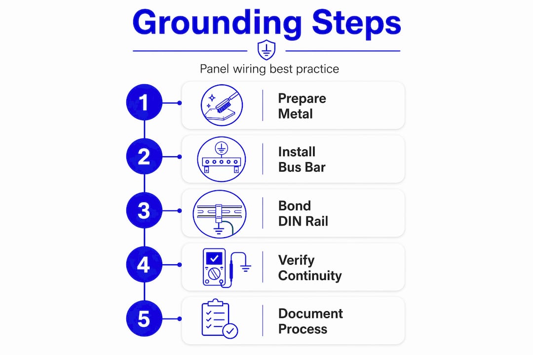
Follow this sequence when you install industrial control panels to build a grounding architecture that is verifiable, redundant, and code-compliant.
-
Mount the enclosure to bare metal. Remove paint or coatings at all four mounting points. Use external tooth lockwashers between the enclosure and the mounting structure to bite through any residual oxidation and maintain metal-to-metal contact.
-
Install the isolated copper ground bus bar. Mount it on insulated standoffs inside the panel so it serves as the single internal grounding reference point. This star-ground approach keeps your internal grounding architecture organized and verifiable.
-
Bond the enclosure to the ground bus. Run a green-jacketed conductor from the enclosure body to the isolated copper bus bar. This conductor, not the mounting bolts alone, establishes the primary bonding path for the enclosure.
-
Install door grounding straps. Every hinged door on the enclosure needs a flexible bonding strap from the door frame to the enclosure body. Door hinges corrode and loosen over time and cannot be relied on as bonding conductors.
-
Prepare steel DIN rails. Remove paint from the rail at grounding block clamping locations. Install grounding blocks clamped directly to the bare rail. Run a jumper wire from each grounding block to the main copper ground bus bar. This creates verifiable, redundant grounding paths rather than relying on incidental contact.
-
Size and run the equipment grounding conductor. The EGC runs from the main copper ground bus back to the source panel’s ground bus. Size it per NEC Table 250.122 based on the rating of the overcurrent protective device. For a 20-amp branch circuit, that is minimum 12 AWG copper. Do not terminate this conductor on a local ground rod.
-
Bond all equipment grounds to the bus. Every device in the panel that has an equipment ground terminal connects to the isolated copper bus bar, not to the DIN rail alone or to the enclosure wall directly.
Pro Tip: Use the Allen-Bradley PLC rack mounting as a reference model for enclosure bonding architecture. Rack-based systems make grounding paths explicit and traceable, which is the same discipline you want for your entire panel.
Compare two common approaches to DIN rail grounding:
| Method | Code compliant | Verifiable | Redundant |
|---|---|---|---|
| Grounding blocks with jumper to bus | Yes | Yes | Yes |
| Relying on rail-to-enclosure contact only | Marginal | No | No |
The second method might pass a visual check but will fail a resistance test and will fail in service as paint and corrosion build up over the panel’s lifetime.
Common mistakes and how to fix them
Most grounding failures in industrial panels come down to a short list of repeatable errors. Recognizing them speeds up both troubleshooting and inspection prep.
-
Paint under fasteners. The most common source of broken continuity is paint left under mounting hardware. The bolt is tight, everything looks solid, but the ground path runs through an insulating layer. Paint and oxidation break continuity even when connections are mechanically secure.
-
Undersized or loose hardware. A ground lug that isn’t torqued to spec, or a grounding block with a loose clamp, creates a high-impedance path. Loose connections cause high-impedance faults that can prevent overcurrent devices from tripping fast enough.
-
Wrong neutral-to-ground bonding location. This is a code trap that catches technicians on subfeeds. Bonding neutral to ground in a subpanel rather than only at the service entrance creates parallel neutral current paths. Dangerous and non-compliant.
-
Relying on floor contact as the only grounding path. Panels should not be isolated from the floor, and floor contact does provide incidental grounding. But floor contact alone is never an engineered bonding path. You still need dedicated conductors.
-
Running EGC to a local ground rod. Local ground rods satisfy lightning protection requirements, not equipment grounding conductor requirements. These are not interchangeable under NEC 250.
Verification protocol: Use a low-resistance ohmmeter to test continuity from every bonding point back to the main ground bus. Target values under 0.1 ohms for any individual connection. Anything above that warrants investigation before the panel leaves the shop.
Pro Tip: Set up a manufacturing quality control checklist as part of your panel build process. Treating grounding verification as a pass/fail quality gate, not an afterthought, catches most of these mistakes before they become field problems.
Long-term reliability and verification standards
A correctly grounded panel is not just compliant on day one. It stays compliant across years of vibration, thermal cycling, and corrosion.
The practices that support long-term reliability include:
- Resistance testing at commissioning and on maintenance intervals. Document baseline values so future readings give you meaningful comparison data.
- Visual inspection of all grounding straps, jumpers, and bus connections at scheduled maintenance intervals. Look specifically for corrosion at bare metal contact points.
- Photo documentation during assembly. Inspectors cannot verify what happened under a closed enclosure lid. Photos taken during build give you proof of process.
- Updated labeling per current NEC and UL 508A requirements. As codes update for 2026 compliance cycles, re-verify that your panel’s documentation reflects current grounding and bonding terminology and conductor sizing.
Multiple grounding paths to building steel, floor contact, and the EGC back to the source are all intentional. Redundancy is a feature, not a problem. Technicians who try to isolate the panel from the floor to prevent theoretical ground loops are typically creating compliance failures without solving any real problem. Reliable bonding architecture with an isolated copper bus bar inside the panel is the right answer.
My honest take on grounding in the field
I’ve worked through enough panel installations and troubleshooting calls to say plainly: the grounding and bonding distinction is the most practically important concept in industrial panel work, and it’s still routinely misunderstood. Not because technicians don’t know the words, but because the failure modes are invisible until something goes wrong.
The over-focus on green screws is a good example. In my experience, technicians often spend time sourcing green grounding hardware when the real issue is a painted DIN rail or a loose bus connection three feet away. The color is for identification. The metal contact is what matters.
I’ve also seen fear of ground loops drive panel installations that deliberately isolate enclosures from the floor. In typical industrial process environments, that fear is not grounded in practical reality. The architecture that actually works is an isolated copper bus bar as the internal star-ground reference, with all bonding paths traceable and verifiable. Floor contact adds incidental redundancy. It doesn’t create problems.
My strongest piece of advice is this: document everything during assembly, not after. The resistance test log and the build photos are not bureaucratic overhead. They are the evidence that protects your installation when something fails two years later and someone asks how the panel was grounded.
— Monica
Get the parts your panel grounding installation needs

When you’re building or maintaining industrial control panels, having the right grounding hardware and automation components on hand matters as much as knowing the code. Industrialpartsusa stocks a wide range of industrial automation parts, including components for control panel builds across GE Fanuc, Allen-Bradley, ABB, and other major platforms. Whether you need replacement I/O modules, bus components, or hard-to-find legacy parts to keep a compliant panel running, Industrialpartsusa ships in-stock items the same day. Their in-house repair and testing capabilities mean sourced parts arrive verified, not just boxed. Browse the full catalog at Industrialpartsusa for grounding-compatible automation components, or check out their guide to obsolete parts sourcing when OEM lead times are not an option.
FAQ
What is the difference between grounding and bonding in a control panel?
Grounding connects the system to earth for voltage stabilization and surge dissipation. Bonding connects metal parts back to the source with a low-impedance path that allows overcurrent devices to trip during a fault.
What size wire do I use for the equipment grounding conductor?
Size the EGC per NEC Table 250.122 based on the rating of the overcurrent protective device protecting the circuit. A 20-amp circuit requires minimum 12 AWG copper; smaller circuits may use 14 AWG.
Can I use aluminum DIN rail as part of the grounding path?
No. Steel DIN rail is code-approved as a grounding conductor when properly bonded with grounding blocks. Aluminum rail is not approved for this purpose under UL 508A.
Why does paint under mounting hardware matter for grounding?
Paint is an insulator. Even a tight mechanical connection through a painted surface can break ground continuity. Remove paint at all bonding contact points and use star washers to maintain metal-to-metal contact.
Should I isolate my control panel enclosure from the plant floor?
Generally, no. Bonding conductors provide the primary fault-current path, and floor contact adds incidental grounding redundancy. Isolating the panel from the floor does not prevent ground loops in typical industrial settings and can create compliance problems.
Recommended
- GE Fanuc IC693CHS391 Industrial Automation Control System Module – Global Electrical and Industrial
- ABB 6246BP10810 Block 115Vac/125Vdc Low Leak Isol I/O with Failed Switch Diagnostics – 8 Circuit – Global Electrical and Industrial
- GE Emerson Genius I/O Industrial Automation Part – IC660BBD024 – Global Electrical and Industrial
- GE Emerson Series 90-30 IC693ALG221 Analog Input 4PT Module – Global Electrical and Industrial