Role of Encoder in Servo System: Engineer’s Guide
An encoder in a servo system is a sensor that detects the motor shaft’s position, speed, and direction, feeding that data back to the drive so the controller can correct any error in real time. The role of encoder in servo system design is not optional or supplementary. It is the mechanism that converts an open-loop motor into a closed-loop precision actuator. Without encoder feedback, a servo drive has no way to verify that commanded motion actually occurred. This guide breaks down how encoders function, which types suit which applications, how resolution and interface electronics affect performance, and what practical decisions engineers face when selecting and installing encoders in manufacturing and automation systems.
How does an encoder work in a servo system?
The closed-loop principle is the foundation of every servo system. The controller sends a position or velocity command to the drive, the drive energizes the motor, and the encoder measures the actual shaft position. That measured value feeds back to the controller, which subtracts it from the commanded position. The resulting error signal enters a PID control loop that adjusts torque output until the error reaches zero. This cycle repeats thousands of times per second.
The function of encoder in servo systems extends beyond simple position reporting. Velocity feedback is derived by differentiating successive position samples, giving the drive real-time speed data without a separate tachometer. Direction is determined by the phase relationship between the encoder’s output channels. Together, these three data streams give the servo drive everything it needs to control motion with sub-millimeter accuracy.
Here is the sequence of events in a single feedback cycle:
- The controller issues a position command to the servo drive.
- The drive applies current to the motor windings, generating torque and shaft rotation.
- The encoder detects the new shaft position and transmits the feedback signal.
- The drive compares actual position to commanded position and calculates the error.
- The PID algorithm adjusts current output to minimize the error on the next cycle.
Pro Tip: If your servo axis exhibits hunting or oscillation at rest, the first thing to check is whether the encoder resolution is high enough for the PID gains you are running. Insufficient resolution creates quantization noise that the controller interprets as real position error, causing it to continuously correct a problem that does not exist.
What are the main encoder types for servo applications?
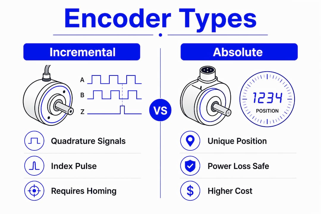
Encoder selection for servo drives comes down to two primary technologies: incremental and absolute. Each has a distinct operating principle, and the choice between them shapes commissioning complexity, safety behavior, and system uptime.
Incremental encoders generate two quadrature signals (A and B channels, 90 degrees out of phase) plus an index pulse (Z channel) once per revolution. The drive counts pulses to track relative position. Incremental encoders typically produce 1,024 to 8,192 pulses per revolution, and quadrature decoding multiplies that count by four, yielding up to 32,768 counts per revolution from an 8,192-line device. The critical limitation is that position data is lost when power is removed. The drive has no memory of where the shaft stopped.
Absolute encoders assign a unique digital code to every shaft position within one revolution (single-turn) or across multiple revolutions (multi-turn). Absolute encoders maintain position through power cycles, so the drive knows exactly where the shaft is the moment power is restored. No homing routine is required.
| Encoder type | Position at power-up | Homing required | Typical cost | Best application |
|---|---|---|---|---|
| Incremental | Unknown | Yes | Lower | General positioning, cost-sensitive axes |
| Absolute (single-turn) | Known within one rev | No | Moderate | Rotary axes, robotic joints |
| Absolute (multi-turn) | Known across revolutions | No | Higher | Linear axes, vertical loads |
| Resolver | Known (analog) | No | Moderate-high | High-temperature, harsh environments |
Beyond these two main categories, resolvers use analog sine and cosine signals rather than digital pulses. They are mechanically robust and tolerate vibration and temperature extremes that would destroy optical encoders. Magnetic encoders use a magnetized target wheel and Hall-effect sensors, offering good dirt and moisture resistance at lower cost than optical designs. Optical encoders provide the highest resolution and accuracy but require clean environments and careful cable management.
Key factors that differentiate encoder types in practice:
- Signal type: Incremental outputs are pulse trains; absolute outputs are digital words (SSI, BiSS-C, EnDat, or HIPERFACE protocols).
- Startup behavior: Incremental systems need a homing sequence every power cycle; absolute systems are ready immediately.
- Safety implications: On vertical or load-carrying axes, losing position at power-down with an incremental encoder can create dangerous drift on restart.
- FOC compatibility: Absolute encoders supply electrical angle data instantly at power-up, which field-oriented control algorithms require. Incremental encoders need an offset-learning procedure before FOC can run correctly.
How do resolution and interface electronics affect servo accuracy?
Resolution sets the finest position increment the servo system can detect and correct. A 2,500-line incremental encoder decoded in quadrature yields 10,000 counts per revolution. On a 10 mm pitch ballscrew, that translates to roughly 1 micrometer of positional resolution. Doubling the encoder line count halves the minimum detectable error, which allows the drive to apply tighter PID gains without inducing instability.
The relationship between resolution and control quality is not linear, though. Encoder resolution and signal quality set fundamental limits on servo loop performance, influencing smoothness, torque ripple, and positioning precision. A high-resolution encoder paired with a noisy or poorly designed interface board will perform worse than a moderate-resolution encoder with a clean signal path.
The encoder interface board is the component that decodes raw encoder signals and delivers processed position data to the servo controller. Signal delay, jitter, or noise in the interface degrades motion quality and can trigger faults. In industrial environments, EMI from variable frequency drives, contactors, and switching power supplies is a constant threat to signal integrity.
Robust interface design addresses this through several techniques:
- Galvanic isolation between the encoder signal lines and the controller bus prevents ground loops and common-mode noise injection.
- Differential signaling (RS-422) rejects common-mode interference over long cable runs, which is why most industrial encoders use differential outputs rather than single-ended TTL.
- Synchronous sampling ensures the controller reads encoder data at a fixed, predictable interval, eliminating timing jitter that would corrupt velocity calculations.
- Hardware filtering on the interface board removes high-frequency noise spikes before they reach the counter logic.
Pro Tip: Keep encoder cables physically separated from power cables by at least 6 inches in cable trays. If they must cross, do so at 90 degrees. This single routing practice eliminates the majority of EMI-induced encoder faults seen in field installations.
For engineers working with legacy GE Fanuc or Allen-Bradley servo systems, understanding how servo drives receive feedback is critical when replacing or upgrading encoder hardware, since interface protocol compatibility determines whether a new encoder will work with an existing drive without additional signal conversion hardware.
What practical factors guide encoder selection in industrial servo systems?
Selecting the right encoder for a manufacturing or automation application requires matching the device to the mechanical, environmental, and control requirements of the axis. Getting this wrong costs time during commissioning and creates reliability problems in production.
Follow this decision sequence when specifying an encoder:
- Define the accuracy requirement. Calculate the minimum position resolution needed at the load, accounting for any mechanical transmission ratio. Work backward to determine the required encoder counts per revolution.
- Assess the environment. Optical encoders require clean, dry conditions. Magnetic or resolver-based devices suit washdown, high-vibration, or high-temperature environments. Check the encoder’s IP rating against the installation location.
- Evaluate safety and restart behavior. Any axis that carries a vertical load, holds a clamping force, or must return to a known position after an e-stop should use an absolute encoder. Choosing absolute vs incremental encoders directly affects commissioning complexity and safety behavior on power loss, particularly on vertical or loaded axes where unexpected motion could be dangerous.
- Check drive compatibility. Confirm that the encoder’s output protocol matches the drive’s feedback input. Synapticon, Beckhoff, and Siemens drives each support specific encoder protocols (EnDat 2.2, BiSS-C, HIPERFACE DSL). Mixing protocols requires an adapter or a different encoder.
- Plan the homing strategy for incremental systems. If budget or availability constrains you to an incremental encoder, design the startup sequence to execute a reliable homing routine before the axis accepts motion commands. Startup sequences must account for incremental encoder position loss and integrate safety interlocks accordingly.
Maintenance considerations are equally important. Optical encoders with glass discs are sensitive to mechanical shock. Check coupling alignment during installation and verify that the encoder shaft is not taking axial or radial loads it was not designed to handle. Magnetic encoders are more forgiving mechanically but can be affected by ferrous contamination near the sensing gap. For troubleshooting, most modern servo drives log encoder fault codes that distinguish between signal loss, excessive noise, and communication errors, giving you a clear starting point for diagnosis.
For industrial drive system basics including encoder selection considerations in the context of broader drive architecture, engineers new to servo commissioning will find the foundational concepts useful before diving into specific encoder specifications.
Key takeaways
Encoder selection and interface quality are the two variables that most directly determine whether a servo system meets its positioning and reliability targets in production.
| Point | Details |
|---|---|
| Closed-loop feedback | Encoders convert open-loop motors into precise closed-loop actuators by reporting real-time position, speed, and direction. |
| Absolute vs incremental | Absolute encoders eliminate homing routines and are mandatory for vertical or safety-critical axes; incremental encoders suit cost-sensitive general positioning. |
| Resolution impact | Higher encoder resolution allows tighter PID gains and finer positioning, but only when paired with a clean, low-jitter interface. |
| Interface electronics | EMI hardening, differential signaling, and synchronous sampling in the interface board directly determine signal integrity and fault rates. |
| FOC compatibility | Absolute encoders supply electrical angle data at power-up, enabling immediate field-oriented control without offset-learning delays. |
What engineers often get wrong about encoder selection
After years of working with servo systems across manufacturing and automation environments, the pattern I see most often is engineers treating encoder selection as a secondary decision. They specify the motor and drive first, then pick whatever encoder fits the budget and mounting interface. That approach works until it doesn’t, and when it fails, the failure mode is subtle. The system runs, but it never quite tunes correctly. Velocity loops are noisy. Positioning repeatability is inconsistent. The integrator spends days adjusting PID gains, never realizing the root cause is a 1,024-line incremental encoder trying to support a high-bandwidth torque loop.
The other mistake I see regularly is underestimating the interface. Engineers focus on the encoder specification and ignore the signal path between the encoder and the controller. A high-resolution absolute encoder running BiSS-C over an unshielded cable routed next to a VFD output is going to produce garbage data. The encoder is not the problem. The installation is. Robust interface design, including isolation, differential signaling, and proper cable routing, is not optional in industrial environments. It is the difference between a system that runs reliably for years and one that generates intermittent faults nobody can explain.
My honest recommendation: if the axis carries any load vertically or requires a known position after an e-stop, specify an absolute encoder from the start. The cost difference over the life of the machine is negligible compared to the commissioning time you save and the safety risk you eliminate.
— Monica
Source your servo system components at Industrialpartsusa

When an encoder fails on a legacy servo axis, lead times from the original manufacturer can stretch weeks or months. Industrialpartsusa stocks new, surplus, and remanufactured automation components including servo motors, motion controllers, and related feedback hardware, with same-day shipping on in-stock items. Their inventory covers GE Fanuc, Allen-Bradley, Mitsubishi, and Omron servo system components, including hard-to-find parts for systems that OEMs no longer actively support. If you are sourcing components for a production line upgrade or an emergency replacement, their automation components catalog is a practical starting point. Every item ships with a one-year warranty backed by in-house testing and repair capabilities.
FAQ
What is the role of an encoder in a servo system?
An encoder provides real-time position, speed, and direction feedback to the servo drive, enabling closed-loop control. The drive compares encoder feedback to the commanded position and uses a PID algorithm to correct any error through torque adjustment.
What is the difference between incremental and absolute encoders?
Incremental encoders count pulses from a reference point and lose position data when power is removed, requiring a homing routine at startup. Absolute encoders assign a unique position code to every shaft angle and retain that data through power cycles, eliminating the need for homing.
How does encoder resolution affect servo performance?
Higher resolution encoders provide finer position data, allowing tighter PID tuning and smoother motion. A 2,500-line encoder decoded in quadrature yields 10,000 counts per revolution, translating to approximately 1 micrometer of resolution on a 10 mm pitch ballscrew.
Why do absolute encoders matter for safety-critical axes?
Absolute encoders maintain position through power loss, so the drive knows the exact shaft location the moment power is restored. On vertical or load-carrying axes, this prevents unexpected motion during restart and eliminates the need for a homing sequence before the axis can accept commands.
What causes encoder-related faults in industrial servo systems?
The most common causes are EMI from nearby VFDs or contactors coupling into unshielded encoder cables, mechanical misalignment loading the encoder shaft, and protocol mismatches between the encoder output and the drive’s feedback input. Differential signaling, proper cable routing, and galvanic isolation in the interface board address the majority of signal-integrity faults.